
Specifications


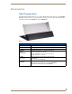
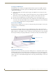


Table Of Contents
- MVP-5100/5150 Modero® ViewPoint® Touch Panels, 5.2" and 5”
- Introduction
- Accessories
- Configuring Communication
- Overview
- IR Communication
- Modero Setup and System Settings
- Wireless Settings - Wireless Access Overview (MVP-5150 Only)
- Configuring Wireless Network Access (MVP-5150 Only)
- Step 1: Configure the Device’s Wireless IP Settings (MVP- 5150 Only)
- Step 2: Configure the Card’s Wireless Security Settings
- Panel Downloads and Firmware Updates
- Setup Pages
- Protected Setup Pages
- Upgrading Firmware
- Programming
- Overview
- Page Commands
- Programming Numbers
- "^" Button Commands
- ^ANI
- ^APF
- ^BAT
- ^BAU
- ^BCB
- ^BCF
- ^BCT
- ^BDO
- ^BFB
- ^BIM
- ^BLN
- ^BMC
- ^BMF
- ^BMI
- ^BML
- ^BMP
- ^BNC
- ^BNN
- ^BNT
- ^BOP
- ^BOR
- ^BOS
- ^BPP
- ^BRD
- ^BSF
- ^BSM
- ^BSO
- ^BSP
- ^BVL
- ^BVN
- ^BVP
- ^BVT
- ^BWW
- ^CPF
- ^DLD
- ^DPF
- ^ENA
- ^FON
- ^GDI
- ^GIV
- ^GLH
- ^GLL
- ^GRD
- ^GRU
- ^GSC
- ^GSN
- ^ICO
- ^IRM
- ^JSB
- ^JSI
- ^JST
- ^MBT
- ^MDC
- ^SHO
- ^TEC
- ^TEF
- ^TOP
- ^TXT
- ^UNI
- Miscellaneous MVP Strings back to the Master
- MVP Panel Lock Passcode commands
- Text Effects Names
- Button Query Commands
- Panel Runtime Operations
- Input Commands
- Embedded codes
- Panel Setup Commands
- Battery Life and Replacement
- Appendix A: Text Formatting
- Appendix B: Wireless Technology
- Appendix C: Troubleshooting
- Overview
- Panel Doesn’t Respond To Touches
- Battery Will Not Hold Or Take A Charge
- MVP Isn’t Appearing In The Online Tree Tab
- MVP Can’t Obtain a DHCP Address
- My WEP Doesn’t Seem To Be Working
- NetLinx Studio Only Detects One Of My Connected Masters
- Can’t Connect To a NetLinx Master
- Only One Modero Panel In My System Shows Up
- Panel Behaves Strangely After Downloading A Panel File Or Firmware
- Overview
Accessories
12
MVP-5100/5150 5.2" Modero Viewpoint Touch Panels
Powering the MVP-TCS-52
The MVP-TCS-52 uses a PS3.0 power supply (included with the touch panel or available separately
from www.amx.com) to provide direct power for the MVP panel both for standard functions and for
charging its internal battery.
1. Connect the terminal end of the PS3.0 power supply to the PWR connector on the bottom of the
MVP-TCS-52.
2. To prevent wear on the power supply cord and assure that the device’s base is in full contact with the
table surface, press the cord into the locking groove running across the bottom of the device.
3. Provide power to the MVP-TCS by connecting the PS3.0 cord to an external power source.
4. Place the touch panel in the Charging Station cradle, guiding it into place with the locking grooves
on each side of the cradle. When fully seated, the touch panel’s charging station connector should be
in contact with the Charging Station’s charger pins (FIG. 4).
Connections and Wiring
The PS3.0 is used to supply power to the device by routing incoming power through the connector pins
and charge the device’s internal battery
Recharging
To recharge the touch panel, slide the device into the Table Charging Station cradle bottom-first and
make sure the device is fully seated in the Charging Station. The charger pins in the bottom of the cradle
(FIG. 4) must be in contact with the connector on the bottom of the touch panel for it to start recharging.
The touch panel will stop recharging automatically once the battery has achieved its maximum charge.
Cleaning the MVP-TCS-52
Always use a clean cotton cloth and a spray bottle containing water or a vinegar-based cleaner to clean
the Table Charging Station, as alcohol-based cleaners can damage the device. Do not directly spray the
device: instead, spray the cloth to prevent moisture from collecting on the charger pins. Do NOT use an
abrasive of any type to clean the Table Charging Station, as this may permanently damage or remove the
device’s finish.
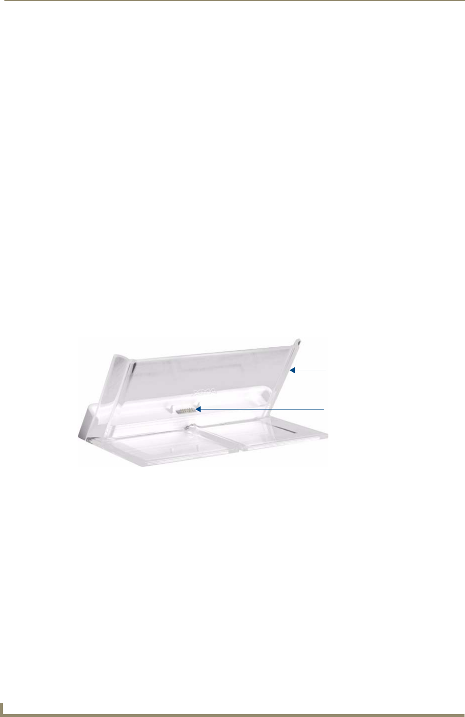
FIG. 4 MVP-TCS-52-GW Table Charging Station - Rear
Charger pins
Charging Station cradle