
Specifications


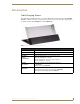


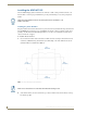
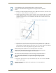
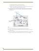
Table Of Contents
- MVP-5100/5150 Modero® ViewPoint® Touch Panels, 5.2" and 5”
- Introduction
- Accessories
- Configuring Communication
- Overview
- IR Communication
- Modero Setup and System Settings
- Wireless Settings - Wireless Access Overview (MVP-5150 Only)
- Configuring Wireless Network Access (MVP-5150 Only)
- Step 1: Configure the Device’s Wireless IP Settings (MVP- 5150 Only)
- Step 2: Configure the Card’s Wireless Security Settings
- Panel Downloads and Firmware Updates
- Setup Pages
- Protected Setup Pages
- Upgrading Firmware
- Programming
- Overview
- Page Commands
- Programming Numbers
- "^" Button Commands
- ^ANI
- ^APF
- ^BAT
- ^BAU
- ^BCB
- ^BCF
- ^BCT
- ^BDO
- ^BFB
- ^BIM
- ^BLN
- ^BMC
- ^BMF
- ^BMI
- ^BML
- ^BMP
- ^BNC
- ^BNN
- ^BNT
- ^BOP
- ^BOR
- ^BOS
- ^BPP
- ^BRD
- ^BSF
- ^BSM
- ^BSO
- ^BSP
- ^BVL
- ^BVN
- ^BVP
- ^BVT
- ^BWW
- ^CPF
- ^DLD
- ^DPF
- ^ENA
- ^FON
- ^GDI
- ^GIV
- ^GLH
- ^GLL
- ^GRD
- ^GRU
- ^GSC
- ^GSN
- ^ICO
- ^IRM
- ^JSB
- ^JSI
- ^JST
- ^MBT
- ^MDC
- ^SHO
- ^TEC
- ^TEF
- ^TOP
- ^TXT
- ^UNI
- Miscellaneous MVP Strings back to the Master
- MVP Panel Lock Passcode commands
- Text Effects Names
- Button Query Commands
- Panel Runtime Operations
- Input Commands
- Embedded codes
- Panel Setup Commands
- Battery Life and Replacement
- Appendix A: Text Formatting
- Appendix B: Wireless Technology
- Appendix C: Troubleshooting
- Overview
- Panel Doesn’t Respond To Touches
- Battery Will Not Hold Or Take A Charge
- MVP Isn’t Appearing In The Online Tree Tab
- MVP Can’t Obtain a DHCP Address
- My WEP Doesn’t Seem To Be Working
- NetLinx Studio Only Detects One Of My Connected Masters
- Can’t Connect To a NetLinx Master
- Only One Modero Panel In My System Shows Up
- Panel Behaves Strangely After Downloading A Panel File Or Firmware
- Overview
Accessories
16
MVP-5100/5150 5.2" Modero Viewpoint Touch Panels
Installing the MVP-WCS-52
Since the Wall Charging Station is intended to be affixed to a wall or other permanent structure, care
must be taken to ensure its proper installation to prevent potential damage to any touch panel placed
within.
Installing the plastic Back Box
The plastic back box has two knockouts at the top of the box and four (4) lockdown wings attached to the
box with Phillips-head screws. For ease of installation, the interior of the box contains an "UP" arrow
pointing to the knockouts. The Metal Rough-In Box does not have to be installed beforehand, but it
offers an extra level of support.
To install the Plastic Back Box:
1. Cut a hole into the wall or surface intended to hold the box. The outer lip of the back box is sized
8.69 inches (220.66mm) long and 6.0 inches (152.4mm) high, so the hole should be at least 1/4"
(6.4mm) smaller in each dimension (FIG. 6).
2. Select the knockout to be removed from the top of the box. The box has two knockouts, at the top
left and the top right.
Other than wall installation tools, the only tool required for this installation is a #1
Phillips screwdriver.
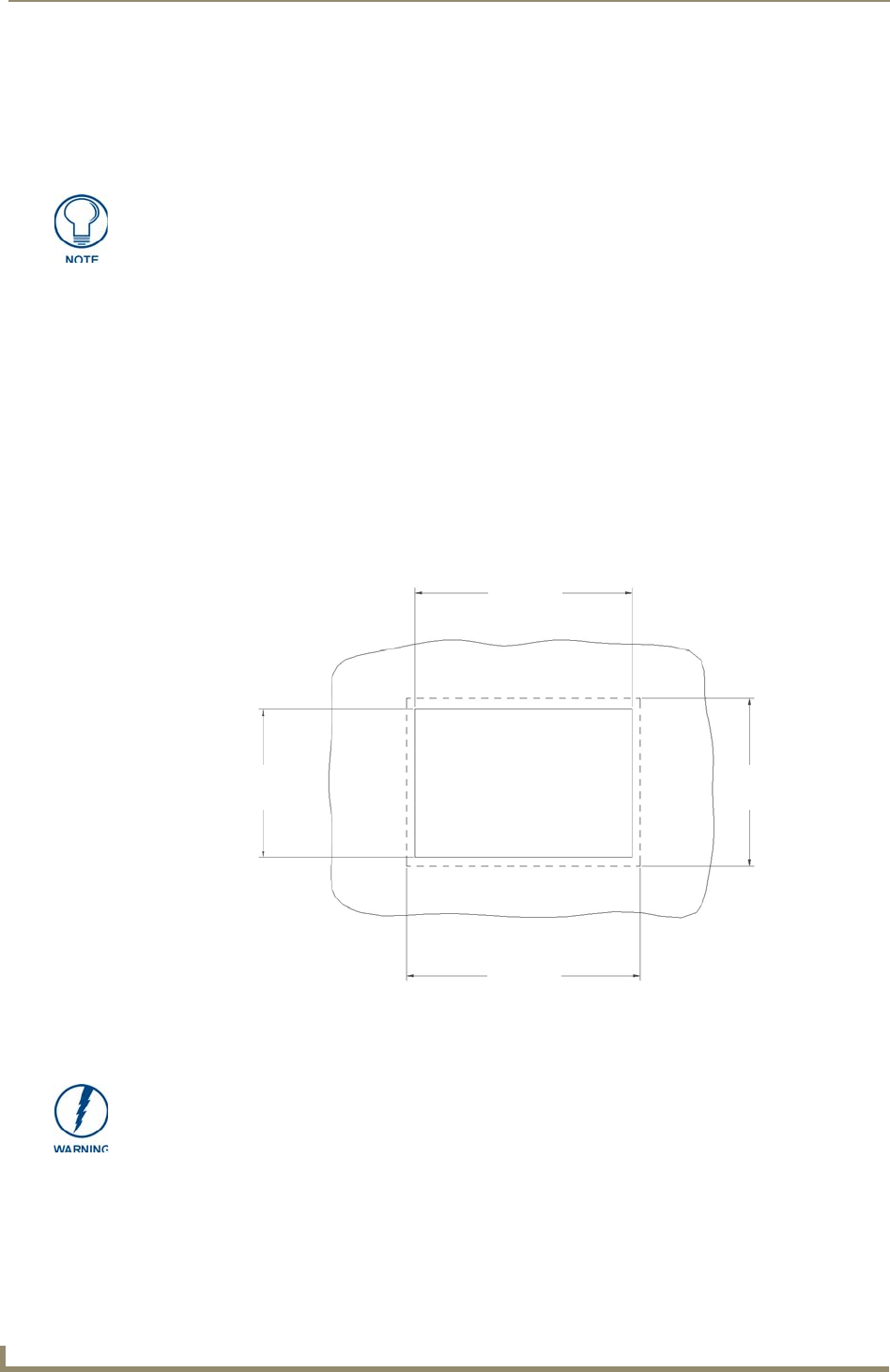
FIG. 6 Recommended cutout for plastic back box
8.25"
(209.55mm)
8.25"
(209.55mm)
5.56"
(141.29mm)
5.56"
(141.29mm)
Make sure to measure the size of the intended hole before starting to cut it.