
Specifications


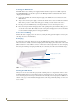


Table Of Contents
- MVP-5100/5150 Modero® ViewPoint® Touch Panels, 5.2" and 5”
- Introduction
- Accessories
- Configuring Communication
- Overview
- IR Communication
- Modero Setup and System Settings
- Wireless Settings - Wireless Access Overview (MVP-5150 Only)
- Configuring Wireless Network Access (MVP-5150 Only)
- Step 1: Configure the Device’s Wireless IP Settings (MVP- 5150 Only)
- Step 2: Configure the Card’s Wireless Security Settings
- Panel Downloads and Firmware Updates
- Setup Pages
- Protected Setup Pages
- Upgrading Firmware
- Programming
- Overview
- Page Commands
- Programming Numbers
- "^" Button Commands
- ^ANI
- ^APF
- ^BAT
- ^BAU
- ^BCB
- ^BCF
- ^BCT
- ^BDO
- ^BFB
- ^BIM
- ^BLN
- ^BMC
- ^BMF
- ^BMI
- ^BML
- ^BMP
- ^BNC
- ^BNN
- ^BNT
- ^BOP
- ^BOR
- ^BOS
- ^BPP
- ^BRD
- ^BSF
- ^BSM
- ^BSO
- ^BSP
- ^BVL
- ^BVN
- ^BVP
- ^BVT
- ^BWW
- ^CPF
- ^DLD
- ^DPF
- ^ENA
- ^FON
- ^GDI
- ^GIV
- ^GLH
- ^GLL
- ^GRD
- ^GRU
- ^GSC
- ^GSN
- ^ICO
- ^IRM
- ^JSB
- ^JSI
- ^JST
- ^MBT
- ^MDC
- ^SHO
- ^TEC
- ^TEF
- ^TOP
- ^TXT
- ^UNI
- Miscellaneous MVP Strings back to the Master
- MVP Panel Lock Passcode commands
- Text Effects Names
- Button Query Commands
- Panel Runtime Operations
- Input Commands
- Embedded codes
- Panel Setup Commands
- Battery Life and Replacement
- Appendix A: Text Formatting
- Appendix B: Wireless Technology
- Appendix C: Troubleshooting
- Overview
- Panel Doesn’t Respond To Touches
- Battery Will Not Hold Or Take A Charge
- MVP Isn’t Appearing In The Online Tree Tab
- MVP Can’t Obtain a DHCP Address
- My WEP Doesn’t Seem To Be Working
- NetLinx Studio Only Detects One Of My Connected Masters
- Can’t Connect To a NetLinx Master
- Only One Modero Panel In My System Shows Up
- Panel Behaves Strangely After Downloading A Panel File Or Firmware
- Overview
Accessories
17
MVP-5100/5150 5.2" Modero Viewpoint Touch Panels
3. Run the power cable through the knockout into the box. Pull out about six inches (15.25cm) of cable
into the box to facilitate installation of the MVP-WCS-52.
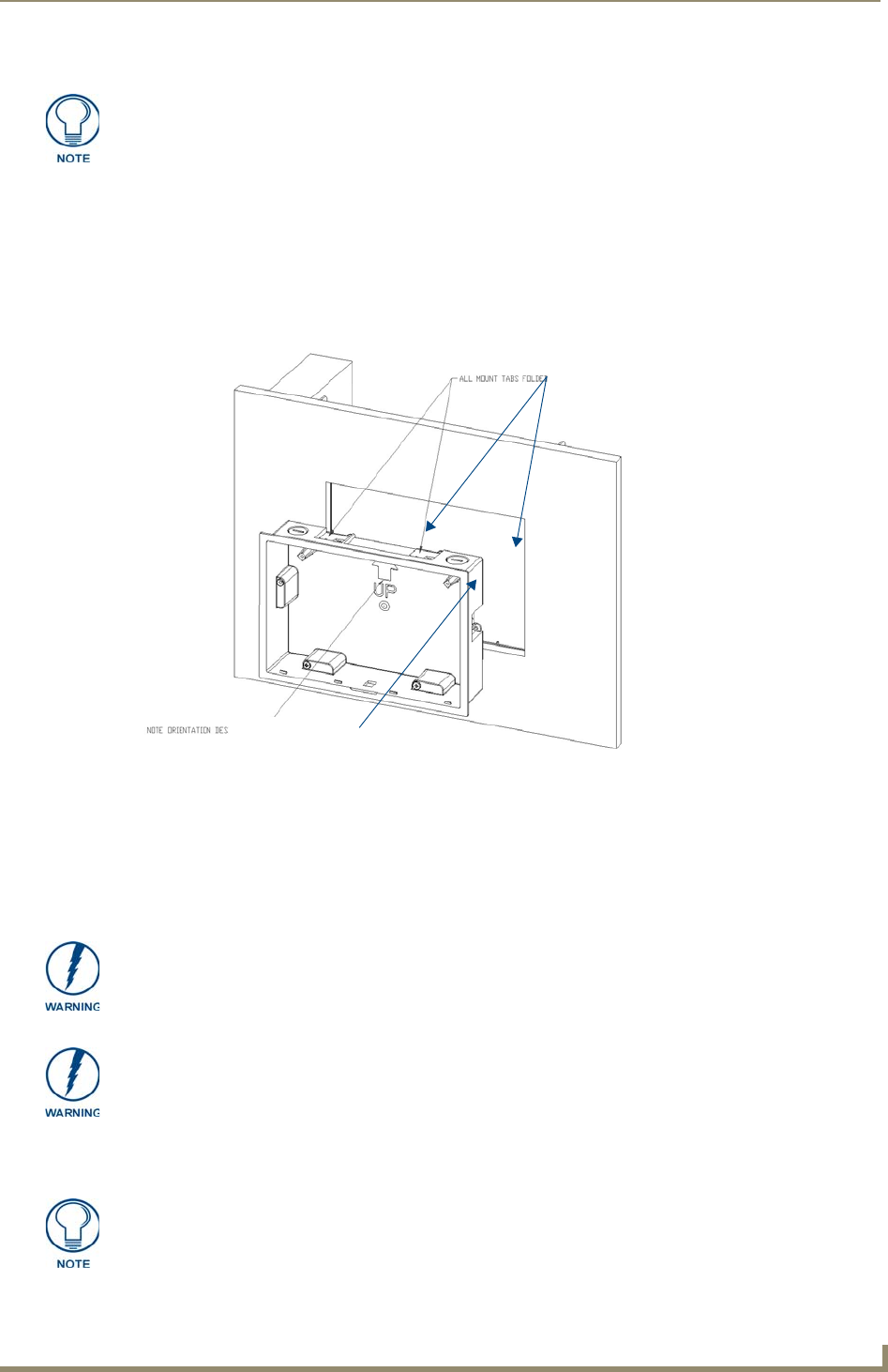
4. Slide the plastic back box into the hole, being careful not to twist or pinch the cable, and set it flush
with the wall (FIG. 7). Make sure that all of the lockdown wings are folded into their slots before
attempting to insert the box. For ease of installation, the inside of the box has the direction "UP"
labeled for reference.
5. Extend the wings on the sides of the box by tightening the screws inside the box. Not all of the
wings must be extended to lock the box in place, but extending a minimum of the top and bottom
wings is highly recommended. Apply enough pressure to the screw head to keep the box flush with
the wall: this ensures that the wing will tighten up against the inside of the wall.
6. Prepare the captive wires for the 2-pin 3.55 mm mini-captive wire connector used for the MVP-
WCS-52’s power supply:
To assist with wiring, and to avoid mechanical stresses on the wire and the
mechanism of the Wall-Mounted Charging Station, the top right knockout is preferred
for use.
FIG. 7 Installation of plastic back box
Note Orientation Designator
All lockdown wings folded flat during installation
Make absolutely certain that the box is in its intended position. Once the box
lockdown wings are extended within the box’s hole within the wall, removing the box
will be extremely difficult without damaging the wall in the process.
The maximum recommended torque to screw in the wings on the plastic back box is
105 IN-OZ [74 N-CM]. Applying excessive torque while tightening the wing screws,
such as with powered screwdrivers, can strip out the wings or damage the plastic
back box.
Preparing and connecting the captive wires requires the use of a wire stripper and
flat-blade screwdriver.