
Specifications


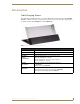


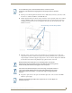
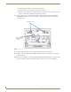
Table Of Contents
- MVP-5100/5150 Modero® ViewPoint® Touch Panels, 5.2" and 5”
- Introduction
- Accessories
- Configuring Communication
- Overview
- IR Communication
- Modero Setup and System Settings
- Wireless Settings - Wireless Access Overview (MVP-5150 Only)
- Configuring Wireless Network Access (MVP-5150 Only)
- Step 1: Configure the Device’s Wireless IP Settings (MVP- 5150 Only)
- Step 2: Configure the Card’s Wireless Security Settings
- Panel Downloads and Firmware Updates
- Setup Pages
- Protected Setup Pages
- Upgrading Firmware
- Programming
- Overview
- Page Commands
- Programming Numbers
- "^" Button Commands
- ^ANI
- ^APF
- ^BAT
- ^BAU
- ^BCB
- ^BCF
- ^BCT
- ^BDO
- ^BFB
- ^BIM
- ^BLN
- ^BMC
- ^BMF
- ^BMI
- ^BML
- ^BMP
- ^BNC
- ^BNN
- ^BNT
- ^BOP
- ^BOR
- ^BOS
- ^BPP
- ^BRD
- ^BSF
- ^BSM
- ^BSO
- ^BSP
- ^BVL
- ^BVN
- ^BVP
- ^BVT
- ^BWW
- ^CPF
- ^DLD
- ^DPF
- ^ENA
- ^FON
- ^GDI
- ^GIV
- ^GLH
- ^GLL
- ^GRD
- ^GRU
- ^GSC
- ^GSN
- ^ICO
- ^IRM
- ^JSB
- ^JSI
- ^JST
- ^MBT
- ^MDC
- ^SHO
- ^TEC
- ^TEF
- ^TOP
- ^TXT
- ^UNI
- Miscellaneous MVP Strings back to the Master
- MVP Panel Lock Passcode commands
- Text Effects Names
- Button Query Commands
- Panel Runtime Operations
- Input Commands
- Embedded codes
- Panel Setup Commands
- Battery Life and Replacement
- Appendix A: Text Formatting
- Appendix B: Wireless Technology
- Appendix C: Troubleshooting
- Overview
- Panel Doesn’t Respond To Touches
- Battery Will Not Hold Or Take A Charge
- MVP Isn’t Appearing In The Online Tree Tab
- MVP Can’t Obtain a DHCP Address
- My WEP Doesn’t Seem To Be Working
- NetLinx Studio Only Detects One Of My Connected Masters
- Can’t Connect To a NetLinx Master
- Only One Modero Panel In My System Shows Up
- Panel Behaves Strangely After Downloading A Panel File Or Firmware
- Overview
Accessories
18
MVP-5100/5150 5.2" Modero Viewpoint Touch Panels
Strip 0.25 inch (6.35 mm) of wire insulation off all wires.
Insert each wire into the appropriate opening on the connector.
Turn the screws clockwise to secure the wires in the connector. Do not over-torque the screws;
doing so can bend the seating pins and damage the connector.
7. Secure the power cable to the device, using either of the two tie-wrap anchors included in the
Installation Kit at the top rear of the device (FIG. 8). Point the head of each tie wrap toward the
center of the device.
8. Firmly seat the mini-captive wire connector to the power connector on the device.
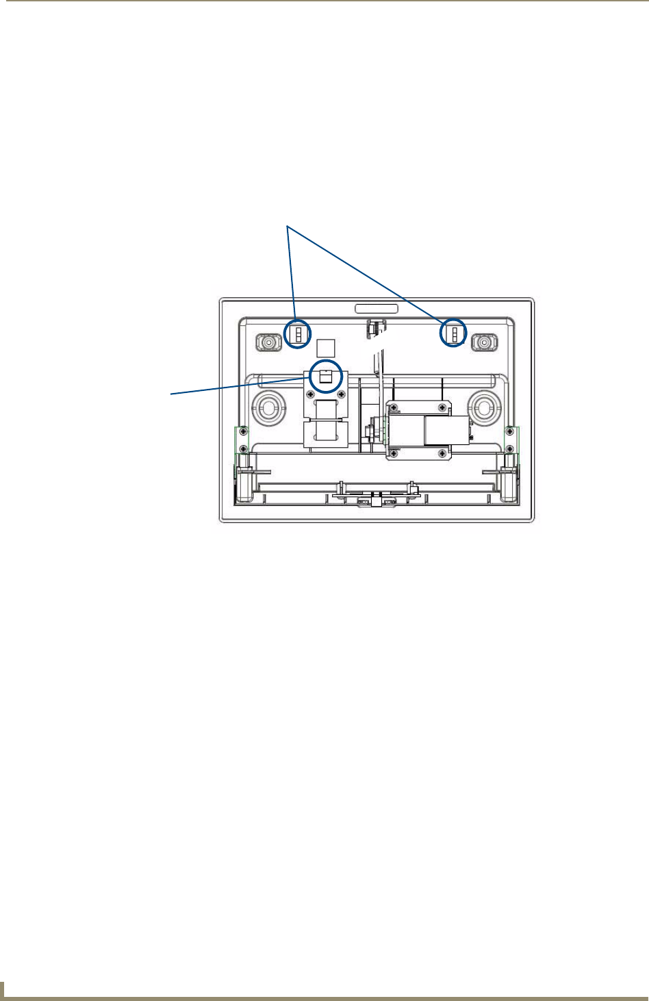
9. Firmly seat the device against the box. Make sure that the tab connector at the top of the device is
locked into the box.
10. Insert the two installation screws from the MVP-WCS-52 Installation Kit into the screw holes in the
interior compartment of the device and tighten them to anchor the device to the box (FIG. 9).
FIG. 8 MVP- WCS-52 - Rear
Tie-Wrap Anchors
Mini-Captive Wire
Connector Plug
(female)