
Specifications

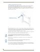

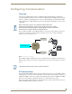
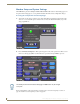

Table Of Contents
- MVP-5100/5150 Modero® ViewPoint® Touch Panels, 5.2" and 5”
- Introduction
- Accessories
- Configuring Communication
- Overview
- IR Communication
- Modero Setup and System Settings
- Wireless Settings - Wireless Access Overview (MVP-5150 Only)
- Configuring Wireless Network Access (MVP-5150 Only)
- Step 1: Configure the Device’s Wireless IP Settings (MVP- 5150 Only)
- Step 2: Configure the Card’s Wireless Security Settings
- Panel Downloads and Firmware Updates
- Setup Pages
- Protected Setup Pages
- Upgrading Firmware
- Programming
- Overview
- Page Commands
- Programming Numbers
- "^" Button Commands
- ^ANI
- ^APF
- ^BAT
- ^BAU
- ^BCB
- ^BCF
- ^BCT
- ^BDO
- ^BFB
- ^BIM
- ^BLN
- ^BMC
- ^BMF
- ^BMI
- ^BML
- ^BMP
- ^BNC
- ^BNN
- ^BNT
- ^BOP
- ^BOR
- ^BOS
- ^BPP
- ^BRD
- ^BSF
- ^BSM
- ^BSO
- ^BSP
- ^BVL
- ^BVN
- ^BVP
- ^BVT
- ^BWW
- ^CPF
- ^DLD
- ^DPF
- ^ENA
- ^FON
- ^GDI
- ^GIV
- ^GLH
- ^GLL
- ^GRD
- ^GRU
- ^GSC
- ^GSN
- ^ICO
- ^IRM
- ^JSB
- ^JSI
- ^JST
- ^MBT
- ^MDC
- ^SHO
- ^TEC
- ^TEF
- ^TOP
- ^TXT
- ^UNI
- Miscellaneous MVP Strings back to the Master
- MVP Panel Lock Passcode commands
- Text Effects Names
- Button Query Commands
- Panel Runtime Operations
- Input Commands
- Embedded codes
- Panel Setup Commands
- Battery Life and Replacement
- Appendix A: Text Formatting
- Appendix B: Wireless Technology
- Appendix C: Troubleshooting
- Overview
- Panel Doesn’t Respond To Touches
- Battery Will Not Hold Or Take A Charge
- MVP Isn’t Appearing In The Online Tree Tab
- MVP Can’t Obtain a DHCP Address
- My WEP Doesn’t Seem To Be Working
- NetLinx Studio Only Detects One Of My Connected Masters
- Can’t Connect To a NetLinx Master
- Only One Modero Panel In My System Shows Up
- Panel Behaves Strangely After Downloading A Panel File Or Firmware
- Overview
Accessories
20
MVP-5100/5150 5.2" Modero Viewpoint Touch Panels
Installing the Optional Metal Rough-In Box
The optional Metal Rough-In Box (FG037-11) is 10 inches (25.40cm) wide at its widest dimension
(wider than the bezel of the Wall Charging Station), and is only intended for pre construction
installations (FIG. 10). The Metal Rough-In Box is used in conjunction with the Wall Charging Station’s
plastic back box. The Metal Rough-In Box must be located behind 3/8" (0.95cm) to 3/4" (1.91cm) of
wall/mounting surface material.
The Metal Rough-In Box bears a wing on each corner which is intended to bridge gaps between studs
and/or spacers. These wings may be bent carefully in order to fit a particular gap, but may not be so bent
as to allow the box to hang in a vertical position. Once placed in the desired position, put at least one
screw through each wing into the adjoining stud or spacer to secure it.
The interior of the box contains a set of holes on either side, as well as top and bottom, for standard 1/4-
inch screws. Use these holes to anchor the box to its adjoining studs or spacers.
The box has two sets of knockouts in the top and bottom, one of the set for US wiring and one for
international wiring.
After completing the installation of the Metal Rough-In Box, install sheet rock or other wall material
over the box, cut a hole matching the size of the inside diameter in the sheet rock, and clean out all dust
before proceeding with the installation of the Plastic Back Box.
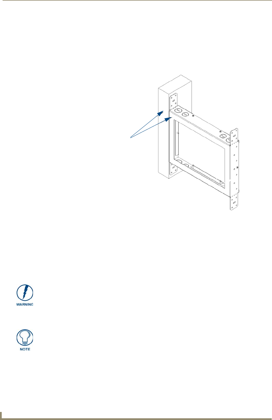
FIG. 10 Typical Metal Rough-In Box Installation
Install front surface of box
flush with surface of wall stud
Ensure that the metal rough-in box is flush with the 2x4 studs. Any overhang will
affect the installation of the covering sheetrock, as well as affect the placement of the
Plastic Back Box.
Make sure that the power cable has been pulled through the metal rough-in box by
the resident electrician before continuing the installation.