
Specifications

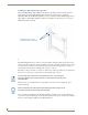

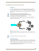
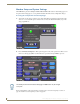

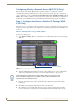
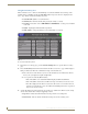
Table Of Contents
- MVP-5100/5150 Modero® ViewPoint® Touch Panels, 5.2" and 5”
- Introduction
- Accessories
- Configuring Communication
- Overview
- IR Communication
- Modero Setup and System Settings
- Wireless Settings - Wireless Access Overview (MVP-5150 Only)
- Configuring Wireless Network Access (MVP-5150 Only)
- Step 1: Configure the Device’s Wireless IP Settings (MVP- 5150 Only)
- Step 2: Configure the Card’s Wireless Security Settings
- Panel Downloads and Firmware Updates
- Setup Pages
- Protected Setup Pages
- Upgrading Firmware
- Programming
- Overview
- Page Commands
- Programming Numbers
- "^" Button Commands
- ^ANI
- ^APF
- ^BAT
- ^BAU
- ^BCB
- ^BCF
- ^BCT
- ^BDO
- ^BFB
- ^BIM
- ^BLN
- ^BMC
- ^BMF
- ^BMI
- ^BML
- ^BMP
- ^BNC
- ^BNN
- ^BNT
- ^BOP
- ^BOR
- ^BOS
- ^BPP
- ^BRD
- ^BSF
- ^BSM
- ^BSO
- ^BSP
- ^BVL
- ^BVN
- ^BVP
- ^BVT
- ^BWW
- ^CPF
- ^DLD
- ^DPF
- ^ENA
- ^FON
- ^GDI
- ^GIV
- ^GLH
- ^GLL
- ^GRD
- ^GRU
- ^GSC
- ^GSN
- ^ICO
- ^IRM
- ^JSB
- ^JSI
- ^JST
- ^MBT
- ^MDC
- ^SHO
- ^TEC
- ^TEF
- ^TOP
- ^TXT
- ^UNI
- Miscellaneous MVP Strings back to the Master
- MVP Panel Lock Passcode commands
- Text Effects Names
- Button Query Commands
- Panel Runtime Operations
- Input Commands
- Embedded codes
- Panel Setup Commands
- Battery Life and Replacement
- Appendix A: Text Formatting
- Appendix B: Wireless Technology
- Appendix C: Troubleshooting
- Overview
- Panel Doesn’t Respond To Touches
- Battery Will Not Hold Or Take A Charge
- MVP Isn’t Appearing In The Online Tree Tab
- MVP Can’t Obtain a DHCP Address
- My WEP Doesn’t Seem To Be Working
- NetLinx Studio Only Detects One Of My Connected Masters
- Can’t Connect To a NetLinx Master
- Only One Modero Panel In My System Shows Up
- Panel Behaves Strangely After Downloading A Panel File Or Firmware
- Overview
Accessories
21
MVP-5100/5150 5.2" Modero Viewpoint Touch Panels
Other MVP-WCS-52 installations
The Wall-Mounted Charging Station is designed to be installed in various different locations, such as
into the face of a wooden podium or the top of a table. Depending upon the ability to wire it to a power
source, Wall-Mounted Charging Stations may be installed on vertical or horizontal surfaces composed of
such materials as wood, brick, and glass.
Installing a Wall-Mounted Charging Station into a solid wall thicker than a standard thickness of
sheetrock is possible, but requires special preparation. If installing into a solid wall of concrete or rock, a
recess must be chiselled or cut out to match the size of the device. The box is sized 8.375 inches
(21.27cm) long and 5.75 inches (14.60cm) high, so the hole should be at least 1/4" (0.64cm) smaller in
these dimensions. To facilitate the full range of movement of the device’s components, the recess must
be at least 2.69 inches (6.83cm) deep.
Ensure that the power cable has been installed in the wall and is accessible by the
installer before chiseling out the recess.
Instead of using the lockdown wings to secure the Plastic Back Box, standard
concrete screws may be inserted through the screw holes after removing the
lockdown wings. However, drill the concrete screw holes into the wall before setting
the screws into the box, as excessive torque applied to the screws will damage the
box. To avoid this, the box may be installed with adhesive. Test an unobtrusive spot
on the back of the box with a sample of the adhesive to check for any adverse
reactions before installing the device.