
Specifications
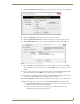
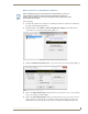
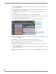
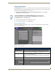

Table Of Contents
- MVP-5100/5150 Modero® ViewPoint® Touch Panels, 5.2" and 5”
- Introduction
- Accessories
- Configuring Communication
- Overview
- IR Communication
- Modero Setup and System Settings
- Wireless Settings - Wireless Access Overview (MVP-5150 Only)
- Configuring Wireless Network Access (MVP-5150 Only)
- Step 1: Configure the Device’s Wireless IP Settings (MVP- 5150 Only)
- Step 2: Configure the Card’s Wireless Security Settings
- Panel Downloads and Firmware Updates
- Setup Pages
- Protected Setup Pages
- Upgrading Firmware
- Programming
- Overview
- Page Commands
- Programming Numbers
- "^" Button Commands
- ^ANI
- ^APF
- ^BAT
- ^BAU
- ^BCB
- ^BCF
- ^BCT
- ^BDO
- ^BFB
- ^BIM
- ^BLN
- ^BMC
- ^BMF
- ^BMI
- ^BML
- ^BMP
- ^BNC
- ^BNN
- ^BNT
- ^BOP
- ^BOR
- ^BOS
- ^BPP
- ^BRD
- ^BSF
- ^BSM
- ^BSO
- ^BSP
- ^BVL
- ^BVN
- ^BVP
- ^BVT
- ^BWW
- ^CPF
- ^DLD
- ^DPF
- ^ENA
- ^FON
- ^GDI
- ^GIV
- ^GLH
- ^GLL
- ^GRD
- ^GRU
- ^GSC
- ^GSN
- ^ICO
- ^IRM
- ^JSB
- ^JSI
- ^JST
- ^MBT
- ^MDC
- ^SHO
- ^TEC
- ^TEF
- ^TOP
- ^TXT
- ^UNI
- Miscellaneous MVP Strings back to the Master
- MVP Panel Lock Passcode commands
- Text Effects Names
- Button Query Commands
- Panel Runtime Operations
- Input Commands
- Embedded codes
- Panel Setup Commands
- Battery Life and Replacement
- Appendix A: Text Formatting
- Appendix B: Wireless Technology
- Appendix C: Troubleshooting
- Overview
- Panel Doesn’t Respond To Touches
- Battery Will Not Hold Or Take A Charge
- MVP Isn’t Appearing In The Online Tree Tab
- MVP Can’t Obtain a DHCP Address
- My WEP Doesn’t Seem To Be Working
- NetLinx Studio Only Detects One Of My Connected Masters
- Can’t Connect To a NetLinx Master
- Only One Modero Panel In My System Shows Up
- Panel Behaves Strangely After Downloading A Panel File Or Firmware
- Overview
Configuring Communication
41
MVP-5100/5150 5.2" Modero Viewpoint Touch Panels
Master Connection to a Virtual Master via Ethernet
Before beginning:
1. Verify that the panel has been configured to communicate with the Access Point and confirm that
the signal strength quality bargraph is On.
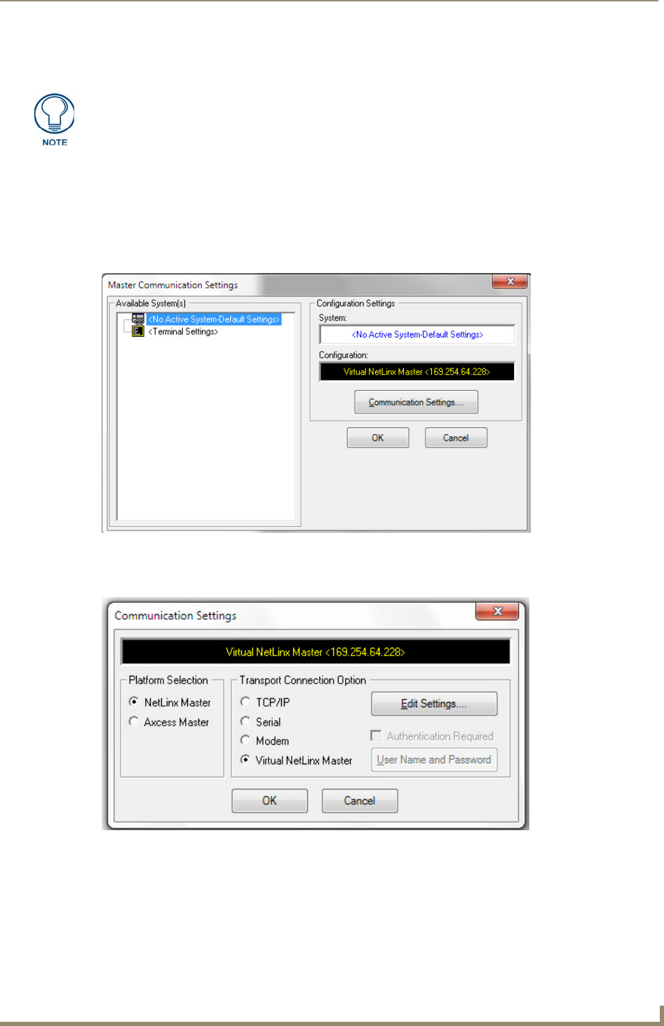
2. In NetLinx Studio, select Settings > Master Communication Settings from the Main menu to
open the Master Communication Settings dialog (FIG. 33).
3. Click the Communications Settings button to open the Communications Settings dialog (FIG. 34).
4. Click on the Virtual NetLinx Master radio button (from the Platform Selection section) to indicate
that you are working as a NetLinx Master.
5. Click on the Virtual NetLinx Master radio box from the Transport Connection Option section to
indicate wanting to configure the PC to communicate with a panel. Everything else, such as the
Authentication, is greyed out because the procedure is not being made through the Master’s UI.
When configuring the panel to communicate with a Virtual Master on your PC via
wireless Ethernet, the Master IP/URL field must be configured to match the IP
Address of the PC. Make sure to use the Virtual System value assigned to the Virtual
Master within NetLinx Studio.
FIG. 33 Master Communications Settings dialog
FIG. 34 Communications Settings dialog