
Specifications
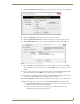
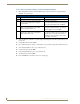
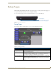
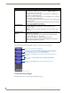
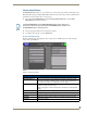

Table Of Contents
- MVP-5100/5150 Modero® ViewPoint® Touch Panels, 5.2" and 5”
- Introduction
- Accessories
- Configuring Communication
- Overview
- IR Communication
- Modero Setup and System Settings
- Wireless Settings - Wireless Access Overview (MVP-5150 Only)
- Configuring Wireless Network Access (MVP-5150 Only)
- Step 1: Configure the Device’s Wireless IP Settings (MVP- 5150 Only)
- Step 2: Configure the Card’s Wireless Security Settings
- Panel Downloads and Firmware Updates
- Setup Pages
- Protected Setup Pages
- Upgrading Firmware
- Programming
- Overview
- Page Commands
- Programming Numbers
- "^" Button Commands
- ^ANI
- ^APF
- ^BAT
- ^BAU
- ^BCB
- ^BCF
- ^BCT
- ^BDO
- ^BFB
- ^BIM
- ^BLN
- ^BMC
- ^BMF
- ^BMI
- ^BML
- ^BMP
- ^BNC
- ^BNN
- ^BNT
- ^BOP
- ^BOR
- ^BOS
- ^BPP
- ^BRD
- ^BSF
- ^BSM
- ^BSO
- ^BSP
- ^BVL
- ^BVN
- ^BVP
- ^BVT
- ^BWW
- ^CPF
- ^DLD
- ^DPF
- ^ENA
- ^FON
- ^GDI
- ^GIV
- ^GLH
- ^GLL
- ^GRD
- ^GRU
- ^GSC
- ^GSN
- ^ICO
- ^IRM
- ^JSB
- ^JSI
- ^JST
- ^MBT
- ^MDC
- ^SHO
- ^TEC
- ^TEF
- ^TOP
- ^TXT
- ^UNI
- Miscellaneous MVP Strings back to the Master
- MVP Panel Lock Passcode commands
- Text Effects Names
- Button Query Commands
- Panel Runtime Operations
- Input Commands
- Embedded codes
- Panel Setup Commands
- Battery Life and Replacement
- Appendix A: Text Formatting
- Appendix B: Wireless Technology
- Appendix C: Troubleshooting
- Overview
- Panel Doesn’t Respond To Touches
- Battery Will Not Hold Or Take A Charge
- MVP Isn’t Appearing In The Online Tree Tab
- MVP Can’t Obtain a DHCP Address
- My WEP Doesn’t Seem To Be Working
- NetLinx Studio Only Detects One Of My Connected Masters
- Can’t Connect To a NetLinx Master
- Only One Modero Panel In My System Shows Up
- Panel Behaves Strangely After Downloading A Panel File Or Firmware
- Overview

Setup Pages
44
MVP-5100/5150 5.2" Modero Viewpoint Touch Panels
Navigation Buttons
The following Navigation buttons (FIG. 38) appear on the left side of the Setup page:
Protected Setup Pages
Information on the Protected Setup pages is available on page 53.
Setup Page (Cont.)
Connection Status: Displays whether the panel has external communication, as well as the
encryption status of the Master, the connection type (
Ethernet or USB), and to
which System the panel is connected.
• Until a connection is established, the message displayed is: “
Attempting via
Ethernet
” or "Attempting via USB".
• When a connection is established, the message displayed is either: “
Connected
via Ethernet
“or “Connected via USB “.
• The word “
Encrypted” appears when an encrypted connection is established with
a NetLinx Master.
Note: The panel must be rebooted before incorporating any panel communication
changes and to detect Ethernet connections.
Panel Brightness: Sets the display brightness levels of the panel.
• Press the Brightness Up/Down buttons to adjust the brightness level.
Range = 0 - 100.
NOTE: Be careful not to turn down the brightness too low to be able to see the
Setup page.
Inactivity Page Flip
Timeout:
Indicates the length of time that the panel can remain idle before automatically
flipping to a pre-selected page.
• Press the Up/Down buttons to increase/decrease the Inactivity Page Flip
Timeout setting. Range = 0 - 240 (minutes).
• Set the timeout value to 0 to disable Inactivity Page Flip mode.
Note: The touch panel page used for the Inactivity page flip is named within a
small Inactivity Page field below the buttons.
FIG. 38 Setup Page Navigation Buttons
Press to access the Protected Setup pages.
Press to access the Project Information page in order to view information on
panel specific information such as resolution and memory.
Press to access the Time page in order to alter the time and date settings on
the Master.
Press to access the Audio page in order to adjust audio parameters
on the panel.
Press to access the
Battery
page in order to monitor battery status in
the panel.
the TPDesign file being used, and Panel Information page in order to view