
Specifications

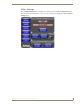
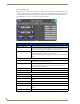
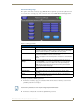
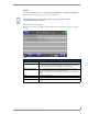
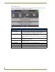
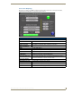

Table Of Contents
- MVP-5100/5150 Modero® ViewPoint® Touch Panels, 5.2" and 5”
- Introduction
- Accessories
- Configuring Communication
- Overview
- IR Communication
- Modero Setup and System Settings
- Wireless Settings - Wireless Access Overview (MVP-5150 Only)
- Configuring Wireless Network Access (MVP-5150 Only)
- Step 1: Configure the Device’s Wireless IP Settings (MVP- 5150 Only)
- Step 2: Configure the Card’s Wireless Security Settings
- Panel Downloads and Firmware Updates
- Setup Pages
- Protected Setup Pages
- Upgrading Firmware
- Programming
- Overview
- Page Commands
- Programming Numbers
- "^" Button Commands
- ^ANI
- ^APF
- ^BAT
- ^BAU
- ^BCB
- ^BCF
- ^BCT
- ^BDO
- ^BFB
- ^BIM
- ^BLN
- ^BMC
- ^BMF
- ^BMI
- ^BML
- ^BMP
- ^BNC
- ^BNN
- ^BNT
- ^BOP
- ^BOR
- ^BOS
- ^BPP
- ^BRD
- ^BSF
- ^BSM
- ^BSO
- ^BSP
- ^BVL
- ^BVN
- ^BVP
- ^BVT
- ^BWW
- ^CPF
- ^DLD
- ^DPF
- ^ENA
- ^FON
- ^GDI
- ^GIV
- ^GLH
- ^GLL
- ^GRD
- ^GRU
- ^GSC
- ^GSN
- ^ICO
- ^IRM
- ^JSB
- ^JSI
- ^JST
- ^MBT
- ^MDC
- ^SHO
- ^TEC
- ^TEF
- ^TOP
- ^TXT
- ^UNI
- Miscellaneous MVP Strings back to the Master
- MVP Panel Lock Passcode commands
- Text Effects Names
- Button Query Commands
- Panel Runtime Operations
- Input Commands
- Embedded codes
- Panel Setup Commands
- Battery Life and Replacement
- Appendix A: Text Formatting
- Appendix B: Wireless Technology
- Appendix C: Troubleshooting
- Overview
- Panel Doesn’t Respond To Touches
- Battery Will Not Hold Or Take A Charge
- MVP Isn’t Appearing In The Online Tree Tab
- MVP Can’t Obtain a DHCP Address
- My WEP Doesn’t Seem To Be Working
- NetLinx Studio Only Detects One Of My Connected Masters
- Can’t Connect To a NetLinx Master
- Only One Modero Panel In My System Shows Up
- Panel Behaves Strangely After Downloading A Panel File Or Firmware
- Overview
Protected Setup Pages
79
MVP-5100/5150 5.2" Modero Viewpoint Touch Panels
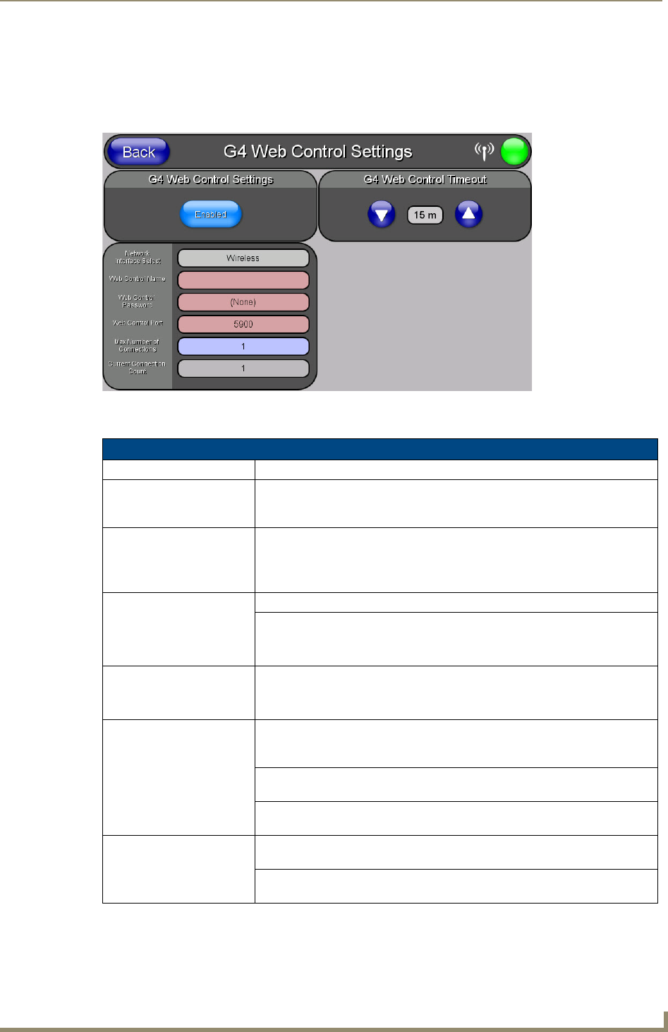
G4 Web Control Settings Page (MVP-5150 only)
An on-board VNC (Virtual Network Computing) server allows the panel to connect to any remote PC running
a VNC client. Once connected, the client can view and control the panel remotely. The options on this page
allow you to enable/disable G4 Web Control functionality(FIG. 57).
Features on this page include:
FIG. 57 G4 Web Control page
G4 Web Control Page
Back: Saves all changes and returns to the previous page.
WiFi/Wired/USB Icon: The icon to the left of the Connection Status Icon displays whether the current
connection to the Master is
Wireless (image of a radio antenna), Wired (image
of three networked computers), or
USB (USB connection symbol).
Connection Status Icon: The icon in the upper-right corner of each Protected Setup page provides a
constant visual indication of current connection status.
Note: a Lock appears on the icon if the panel is connected to a secured NetLinx
Master.
G4 Web Control Settings: Sets the IP communication values for the touch panel:
Enable/Enabled: The Enable/Enabled button toggles between the two G4 activation settings:
• Enable - deactivates G4 Web Control on the panel.
• Enabled - activates G4 Web Control on the panel.
Network Interface Select: Toggles between the two network interface options:
• Wireless - the panel is communicating via an Access Point (AP).
• Wired - the panel is communicating via its mini-USB port.
Web Control Name: Use this field to enter a unique alpha-numeric string to be used as the panel’s
display name within the
Manage WebControl Connections window of the
NetLinx Security browser window.
Web Control Password: Use this field to enter the G4 Authentication session password required for
VNC access to the panel.
Web Control Port: Use this field to enter the number of the port used by the VNC Web Server.
Default = 5900.
Maximum Number of
Connections:
Displays the maximum number of users that can be simultaneously connected
to this panel via VNC. Default = 1.
Current Connection
Count:
Displays the number of users currently connected to this panel via VNC.