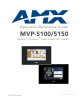
Operation/Reference Guide MVP-5100/5150 Modero® ViewPoint® Touch Panels, 5.
AMX Limited Warranty and Disclaimer This Limited Warranty and Disclaimer extends only to products purchased directly from AMX or an AMX Authorized Partner which include AMX Dealers, Distributors, VIP’s or other AMX authorized entity.
AMX Software License and Warranty Agreement • LICENSE GRANT. AMX grants to Licensee the non-exclusive right to use the AMX Software in the manner described in this License. The AMX Software is licensed, not sold. This license does not grant Licensee the right to create derivative works of the AMX Software. The AMX Software consists of generally available programming and development software, product documentation, sample applications, tools and utilities, and miscellaneous technical information.
Table of Contents Table of Contents Introduction ........................................................................................................1 MVP-5150 Modero® ViewPoint® Wi-Fi Touch Panel, 5.2" and 5" ........................... 1 Common Application....................................................................................................... 1 Features ..........................................................................................................................
Table of Contents DHCP............................................................................................................................. 25 Configuring Wireless Network Access (MVP-5150 Only) ........................................ 26 Step 1: Configure the Device’s Wireless IP Settings (MVP-5150 Only) ................... 26 Wireless cOmmunication Using a DHCP Address .......................................................... 26 Wireless Communication Using a Static IP Address..................
Table of Contents EAP-FAST ...................................................................................................................... 69 EAP-PEAP...................................................................................................................... 71 EAP-TTLS Settings......................................................................................................... 73 EAP-TLS Settings..........................................................................................
Table of Contents PAGE ...................................................................................................................................... PPOF....................................................................................................................................... PPOG ...................................................................................................................................... PPON ....................................................................
Table of Contents ^GIV ........................................................................................................................................ ^GLH ....................................................................................................................................... ^GLL........................................................................................................................................ ^GRD.................................................................
Table of Contents AKEYB .................................................................................................................................... AKEYP..................................................................................................................................... AKEYR..................................................................................................................................... @AKP .......................................................................
Table of Contents Text Area Input Masking....................................................................................... 158 Input mask character types ......................................................................................... 158 Input Mask Ranges ...................................................................................................... 159 Input mask next field characters .................................................................................
Table of Contents viii MVP-5100/5150 5.
Introduction Introduction MVP-5150 Modero® ViewPoint® Wi-Fi Touch Panel, 5.2" and 5" The MVP-5150 delivers high-end style and just the right features in a sleek, sexy, ultra-compact design. The MVP-5150 is perfect for installations desiring the sleek design of the MVP-5200i, but do not need all of its features. The MVP-5150 offers both Wi-Fi and one-way IR communication giving the user instant control of virtually any device in the home or office (FIG. 1). The MVP-5150 is available in two models: 5.
Introduction Product Specifications MVP-5150 Product Specifications Dimensions: 4 3/4" x 7 9/16" x 13/16" (120.7 mm x 191.8 mm x 20.3 mm) Weight: • 1.25 lbs (0.57 kg) Enclosure: Matte black plastic. Power Requirements (Without Charging): FG5966-07, Panel with battery fully charged or with no battery: • Constant current draw: 0.3 A @ 12 VDC • Startup current draw: 0.4 A @ 12 VDC FG5966-09, Panel with battery fully charged or with no battery: • Constant current draw: 0.
Introduction MVP-5150 Specifications (Cont.) Panel LCD Parameters (Cont.): Type: WVGA Aspect Ratio (WH): 16:9 Brightness (luminance): 300 cd/m2 Channel transparency: 8-bit Alpha blending Contrast ratio: • FG5966-07: 400:1 • FG5966-09: 600:1 Display colors: • FG5966-07: 262,144 colors (18-bit color depth) • FG5966-09: 16M colors (24-bit color depth) Dot/pixel pitch: • FG5966-07: 0.
Introduction MVP-5150 Specifications (Cont.
Introduction MVP-5100 5.2" Modero ViewPoint IR Touch Panel The MVP-5100 is a 5.2" Touch Panel built on the same lightning-fast processor as the MVP-5200i and offers the same eye-popping, crisp, clean, high-resolution graphics in an ultra-light compact design that is easy to carry. The MVP-5100 is perfect for installations desiring the sleek design of the MVP-5150, but not requiring wireless capability.
Introduction The MVP-5100 differs from the MVP-5150 in that it does not have a built-in wireless card or the capacity to install one, and only communicates with other devices via IR. Otherwise, the two devices are identical. Product Specifications MVP-5100 Specifications (FG5966-08) Dimensions: 4 3/4" x 7 9/16" x 13/16" (120.7 mm x 191.8 mm x 20.3 mm) Weight: • 1.25 lbs (0.57 kg) Enclosure: Matte black plastic.
Introduction MVP-5100 Specifications (FG5966-08) (Cont.) Panel LCD Parameters: • Size: 5.2" (13.21 cm) • Type: WVGA • Aspect ratio: 16 x 9 • Brightness (luminance): 300 cd/m2 • Channel transparency: 8-bit Alpha blending • Contrast ratio: 20:1 • Display colors: 262,144 colors (18-bit color depth) • Dot/pixel pitch: 0.
Introduction (FIG. 1 and FIG. 2). The mini-USB port is only used for uploading firmware to the device. It cannot be used for headphones, speakers, receiving power, or any other function. Transferring firmware KIT files over a direct USB connection should only be done when the panel is connected to a power supply. If battery power fails during a firmware upgrade, the panel flash file system may become corrupted.
Introduction Cleaning the Touch Overlay and Case Always use a clean cotton cloth and a spray bottle containing water or a vinegar-based cleaner when cleaning the device, as alcohol-based cleaners can damage the device’s touch screen overlay. Do not directly spray the device: instead, spray the cloth to clean the touch screen overlay. Do NOT use an abrasive of any type to clean the device, as this may permanently damage or remove the device’s finish. MVP-5100/5150 5.
Introduction 10 MVP-5100/5150 5.
Accessories Accessories Table Charging Station The MVP-5100 and MVP-5150 may be used with the MVP-TCS-52 Table Charging Station (FG59661X) (FIG. 3), which acts both as a charging station and a direct power connection. The charging station is available in either white (FG5966-10) or black (FG5966-11). FIG. 3 MVP-TCS-52-GB Table Charging Station - Front MVP-TCS-52 Specifications Dimensions (HWD): 8.0” x 4.75” x 3.5” (20.32cm x 12.07cm x 8.89cm) Weight: .65 lbs (.
Accessories Powering the MVP-TCS-52 The MVP-TCS-52 uses a PS3.0 power supply (included with the touch panel or available separately from www.amx.com) to provide direct power for the MVP panel both for standard functions and for charging its internal battery. 1. Connect the terminal end of the PS3.0 power supply to the PWR connector on the bottom of the MVP-TCS-52. 2.
Accessories Wall Charging Station The optional MVP-WCS-52 Wall Charging Station (FG5966-1X) offers the same recharging and connection features as the Table Charging Station, with the advantage of being placed within accessible locations where the table station is either inconvenient or impractical (FIG. 5). The Wall Charging Station is available in either white (FG5966-13) or black (FG5966-12). MVP-WCS-52 MVP-5100 Security Release button FIG.
Accessories MVP-WCS-52 Specifications (Cont.) Front Panel Components: • Securing Magnets: Prevent MVP touch panel from falling free during ejection. • Security Latch: Adds the primary layer of security when mounting an MVP touch panel. When the device is inserted, this latch grabs onto the rear of the touch panel and secures it to prevent it from being removed. • Interface Connector Pins: A set of retractable pins (male) that connect to the underside MVP connector strip.
Accessories Unique passwords may be entered for up to four unique users as well as the administrator. For more information on setting passwords, please refer to the Password Settings Page section on page 83. Recharging To recharge the touch panel: 1. Slide the device into the Wall Charging Station cradle bottom-first and make sure the device is fully seated in the Charging Station. 2. Press the top of the touch panel back until it clicks.
Accessories Installing the MVP-WCS-52 Since the Wall Charging Station is intended to be affixed to a wall or other permanent structure, care must be taken to ensure its proper installation to prevent potential damage to any touch panel placed within. Other than wall installation tools, the only tool required for this installation is a #1 Phillips screwdriver.
Accessories To assist with wiring, and to avoid mechanical stresses on the wire and the mechanism of the Wall-Mounted Charging Station, the top right knockout is preferred for use. 3. Run the power cable through the knockout into the box. Pull out about six inches (15.25cm) of cable into the box to facilitate installation of the MVP-WCS-52. 4. Slide the plastic back box into the hole, being careful not to twist or pinch the cable, and set it flush with the wall (FIG. 7).
Accessories Strip 0.25 inch (6.35 mm) of wire insulation off all wires. Insert each wire into the appropriate opening on the connector. Turn the screws clockwise to secure the wires in the connector. Do not over-torque the screws; doing so can bend the seating pins and damage the connector. 7. Secure the power cable to the device, using either of the two tie-wrap anchors included in the Installation Kit at the top rear of the device (FIG. 8).
Accessories Screw holes Plastic back box Neodymium magnets MVP-WCS-52 Rubber feet FIG. 9 Installation of MVP-WCS-52 For ease of installation, put each screw on a neodymium magnet in the device’s interior compartment to keep them on hand until they are needed. 11. After fully seating the screws, wipe down the area around the screw holes with the alcohol prep pad from the Installation Kit. Take a rubber foot and remove its adhesive backing.
Accessories Installing the Optional Metal Rough-In Box The optional Metal Rough-In Box (FG037-11) is 10 inches (25.40cm) wide at its widest dimension (wider than the bezel of the Wall Charging Station), and is only intended for pre construction installations (FIG. 10). The Metal Rough-In Box is used in conjunction with the Wall Charging Station’s plastic back box. The Metal Rough-In Box must be located behind 3/8" (0.95cm) to 3/4" (1.91cm) of wall/mounting surface material.
Accessories Other MVP-WCS-52 installations The Wall-Mounted Charging Station is designed to be installed in various different locations, such as into the face of a wooden podium or the top of a table. Depending upon the ability to wire it to a power source, Wall-Mounted Charging Stations may be installed on vertical or horizontal surfaces composed of such materials as wood, brick, and glass.
Accessories 22 MVP-5100/5150 5.
Configuring Communication Configuring Communication Overview All control for a MVP-5150 touch panel is established through a NetLinx Master. Communication between the MVP and the Master consists of using either Wireless Ethernet (DHCP, Static IP) or USB. References to Ethernet in this manual focus on the use of Wireless Ethernet via the MVP-5150’s WiFi Card. Configuration for a MVP-5100 touch panel is made through the mini-USB port, as it does not have a WiFi Card.
Configuring Communication Modero Setup and System Settings All AMX Modero panels, including the MVP-5100 and MVP-5150, feature on-board Setup pages. Use the options in the Setup pages to access panel information and make various configuration changes. Accessing the Setup and Protected Setup Pages 1. At any time, use the device’s stylus to press down and hold the reset button on the left side of the device for 3-5 seconds.
Configuring Communication Setting the Panel’s Device Number In the Protected Setup page: 1. Press the Device Number field in the Device ID section to open the Device Number keypad. 2. Enter a unique Device Number assignment for the device, and press Done to return to the Protected Setup page. The Device Number range is 1 - 32000, with the Master assigning the panel a new Device Name once connected, and the default is 0. 3. Press Reboot to reboot the device and apply the new Device Number.
Configuring Communication Configuring Wireless Network Access (MVP-5150 Only) The first step in connecting the MVP-5150 to a wireless network is to configure the wireless communication parameters within the device’s Wireless Settings page. This page only configures the card to communicate to a target AP: the device must still be directed to communicate with the correct Master.
Configuring Communication This information can be found in either the Workspace - System name > Define Device section of the code that defines the properties for the panel, or in the Device Addressing/Network Addresses section of the Tools > NetLinx Diagnostics dialog. 6. Set up the security and communication parameters between the wireless card and the target AP by configuring the Wireless Settings section on this page.
Configuring Communication Using the Site Survey Tool This tool allows a user to "sniff out" all transmitting Access Points within the detection range of the internal wireless card (FIG. 15).
Configuring Communication If the panel detects more than 10 APs, the Up/Down arrows at the far right side of the page become active (blue) and allow the user to scroll through the list of entries. 4. Select a desired Access Point by touching the corresponding row. The up arrow and down arrow will be grayed out if ten or fewer access points are detected. If more are detected, then they will be enabled as appropriate so that the user can scroll through the list. 5.
Configuring Communication Connecting to the AP begins the communication FIG. 17 Site Survey of available APS (Unsecured AP shown selected) Manually entering the SSID information into the appropriate fields by following steps 7 through 9. 3. From within the Information/Configuration section, press the Simple button to open the Wireless Security: Simple Mode popup window (FIG. 18). An Open security method does not utilize any encryption methodology, but does require that an alpha-numeric SSID be entered.
Configuring Communication 9. Press the Back button to return to the Protected Setup page and press the on-screen Reboot button to save any changes and restart the device. Remember that the connection must be configured to a target Master from the System Settings page. 10. After the panel restarts, return to the Wireless Settings page’s Information/Configuration section and verify the signal level value and signal level.
Configuring Communication Manually Setting SSID From the Protected Setup page: 1. Select Wireless Settings. 2. From the Information/Configuration section of the Wireless Settings page, press the Simple button to open the Wireless Security: Simple Mode popup window (FIG. 20). Encryption button (disabled in Open) FIG. 20 Wireless Security page 3. Press the Security Type field to select WEP. 4. Press the SSID field.
Configuring Communication FIG. 21 WEP Key # Keyboard 8. If entering a Current Key generated either by the target AP or another Modero panel, within the WEP Keys section, touch the Key # button to launch the WEP Key # keyboard (FIG. 21), enter the characters and press Done when finished. This Key value corresponds to the Default WEP Key number used on the Access Point and selected in the Default Key field. 9. The remaining Current Key field is greyed-out and cannot be altered by the user.
Configuring Communication Panel Downloads and Firmware Updates The MVP-5100 and MVP-5150 devices support a USB driver for panel downloads and firmware updates. This means that the devices connect to a host computer for updates through their Mini USB ports (FIG. 22). All touch panel setup is done through NetLinx Studio and TPDesign4. Mini-USB Port FIG. 22 USB Port on the MVP-5100/5150 Firmware downloads require use of the USB Programming Cable (FG10-5965) and a computer running Windows XP.
Configuring Communication Under Subnet mask, set the suitable subnet mask. Click OK. 7. In the next box (FIG. 24), make sure to: Select Search for the best driver in these locations. Select Include this location in the search. Click on Browse. Select the folder that contains the 'linux.inf' file. FIG. 24 Found New Hardware Wizard Installation Options dialog 8. Click Next. 9. The Windows XP machine now searches for the suitable driver (FIG. 25). FIG.
Configuring Communication 10. Once the system finds the driver, it displays its choice (FIG. 26). Click Finish to complete the driver installation. FIG. 26 Completing the Found New Hardware Wizard The USB interface will require a static IP address. Proceed to the next steps to set up the IP address on the USB interface. In Windows XP: 1. From the Windows XP desktop, click on Start > Control Panel > Network Connections > Local Area Connection.
Configuring Communication 4. In the Local Area Connection Properties window (FIG. 27) under the General tab, select Internet Protocol (TCP/IP) and click on Properties to open the Internet Protocol (TCP/IP) Properties window. (FIG. 28) FIG. 28 Internet Protocol (TCP/IP) Properties 5. In the new window: Select Use the following IP Address. Under IP address, provide an IP address, ensure that it is in the same subnet as the IP address given to the USB interface on the device.
Configuring Communication Do not set USB to the same subnet address as the Ethernet card. 6. In the Local Area Connection Properties window, click on OK. The user should now be able to run any TCP/IP application between the two systems. After this initial setup, the device may be configured solely by downloading the latest TPDesign4 file. Configure a Virtual NetLinx Master via USB A Virtual NetLinx Master (VNM) is used when the target panel is not actually connected to a physical NetLinx Master.
Configuring Communication 3. Click the Communications Settings button to open the Communications Settings dialog (FIG. 31). FIG. 31 Communications Settings dialog 4. Click the NetLinx Master radio button in the Platform Selection section. 5. Click the Virtual NetLinx Master radio button in the Transport Connection Option section. 6. Click the Edit Settings button to open the Virtual NetLinx Master Settings dialog (FIG. 32). FIG. 32 Virtual NetLinx Master Settings dialog box 7.
Configuring Communication Connecting to the NetLinx Master via Ethernet (MVP-5150 Only) 1. When using Wireless Ethernet with the MVP-5150, press the listed Mode to toggle through the available connection modes: Connection Modes Mode Description Procedures None No connection None Auto The device connects to the first master that responds. This setting requires setting the System Number. Setting the System Number: The device connects to the specific IP of a Master via a TCP connection.
Configuring Communication Master Connection to a Virtual Master via Ethernet When configuring the panel to communicate with a Virtual Master on your PC via wireless Ethernet, the Master IP/URL field must be configured to match the IP Address of the PC. Make sure to use the Virtual System value assigned to the Virtual Master within NetLinx Studio. Before beginning: 1. Verify that the panel has been configured to communicate with the Access Point and confirm that the signal strength quality bargraph is On.
Configuring Communication 6. Click the Edit Settings button in the Communications Settings dialog to open the Virtual NetLinx Master Settings dialog. 7. From within this dialog, enter a unique System number (default is 1) and note the IP Address of the target PC being used as the Virtual Master. 8. Click OK to close the open dialogs, save the settings, and return to the main NetLinx Studio application. 9. Place the panel in the Table Charging Station or in the Wall Charging Station. 10.
Setup Pages Setup Pages Both the MVP-5100 and MVP-5150 feature on-board Setup pages. Use the options in the Setup pages to access panel information and make various configuration changes. To access the Setup pages, press the reset button and hold for 3 to 5 seconds (FIG. 36). Reset button: Press and hold for 3 seconds to access the Setup pages. FIG. 36 Setup Page Access buttons Setup Pages The Setup page (FIG. 37) allows quick access to several essential panel properties: FIG.
Setup Pages Setup Page (Cont.) Connection Status: Displays whether the panel has external communication, as well as the encryption status of the Master, the connection type (Ethernet or USB), and to which System the panel is connected. • Until a connection is established, the message displayed is: “Attempting via Ethernet” or "Attempting via USB". • When a connection is established, the message displayed is either: “Connected via Ethernet “or “Connected via USB “.
Setup Pages Information Button The Information button allows access of both the Project Information page, which contains data on the TPDesign4 file being used with the MVP-5100, and the Panel Information page, which contains detailed information on the panel itself. To access these pages: 1. Press and hold the Information button until the Project Information button and the Panel Information button slide from the left.
Setup Pages Project Information Page (Cont.) Sales Order: Displays the sales order information. Purchase Order: Displays the purchase order information. AMX IR 38K Assigned Port: Displays the AMX 38 kHz IR channel port used by the IR Emitter on the panel. • This information is specified in TPD4 (Project Properties > IR Emitters & Receivers tab).
Setup Pages Panel Information Page The Panel Information page provides detailed panel information (FIG. 40). FIG. 40 Panel Information page Features on this page include: Panel Information Page Back: Saves all changes and returns to the previous page. WiFi/Wired/USB Icon: The icon to the left of the Connection Status Icon displays whether the current connection to the Master is Wireless (image of a radio antenna), Wired (image of three networked computers), or USB (USB connection symbol).
Setup Pages Panel Information Page (Cont.) 48 File System: Displays the amount of Compact Flash memory available on the panel. RAM: Displays the available RAM (or Extended Memory module) on the panel. Panel Start Time: Displays the time the panel last started or rebooted. Bulb Hours: Displays the number of hours elapsed with the display on full power. MVP-5100/5150 5.
Setup Pages Time & Date Settings Page The options on the Time & Date Settings page (FIG. 41) allows setting and adjusting of time and date information on the NetLinx Master. If the time and/or date on the Master is modified, all connected devices will be updated to reflect the new information. FIG. 41 Time and Date Setup page Both touch panels do not have an on-board clock, so the only way to modify a panel’s time without altering the Master is via NetLinx Code.
Setup Pages Audio Settings Page The Audio Settings page allows adjustment of volume levels and panel sounds settings (FIG. 42). FIG. 42 Audio Settings pages Features on these pages include: Audio Settings Page Back: Saves all changes and returns to the previous page.
Setup Pages Power Management Page The options on the Power Management page allow setting of power warning preferences and battery status information, and adjustment of the display times for battery warnings (FIG. 43). FIG. 43 Battery page Features on this page include: Power Management Page Back: Saves all changes and returns to the previous page.
Setup Pages Power Management Page (Cont.) Shutdown: This value determines the number of hours or minutes that need to pass before the panel automatically shuts down. Once shut down, the device will have to be restarted. The Up/Down buttons alter the timeout value (in minutes). Use the Up/Down arrows to change the settings. A value of Off disables this feature.
Protected Setup Pages Protected Setup Pages The Protected Setup page (FIG. 44) provides secured access to advanced panel configuration options, including communication and security settings. The Protected Setup page is accessed through the Setup page (please refer to the Setup Pages section on page 43). To access the Protected Setup pages: 1. Press the reset button and hold for 3 to 5 seconds to access the Setup pages. 2. Select the Protected Setup button on the left side of the screen. 3.
Protected Setup Pages Protected Setup Page (Cont.) Docking Station • Dock Status - Illuminates when the panel is docked and communicating with the Charging Station. • Undock Panel - Releases panel from Wall Mounted Charging Station. Options: • Function Show - toggles the display of the channel port, channel code, level port and level code on all touch panel buttons (see FIG. 45). • Telnet - enables or disables the panel’s telnet server, allowing or preventing direct telnet communication to the panel.
Protected Setup Pages The Protected Setup page for the MVP-5100 is slightly different, as some of the functions are disabled (FIG. 46). The particular functions that are disabled are explained in detail in the Protected Setup Navigation Buttons section on page 57. FIG. 46 Protected Setup page for the MVP-5100 Rebooting and shutting down the touch panel To reboot either the MVP-5100 or the MVP-5150: 1. Access the Protected Setup page. 2. Press the Reboot button. 3.
Protected Setup Pages Security Settings (MVP-5150 only) The Security button on the Protected Setup page of the MVP-5150 has three settings: Standard, Secure, and DoD. Pressing the button opens the Panel Security Setting popup window (FIG. 47) FIG. 47 Panel Security Setting popup window Each of the settings has different features for touch panel security: Security Profile Features Standard: • Factory default, shipped in this configuration. • Default Protected Setup Password is “1988”.
Protected Setup Pages Protected Setup Navigation Buttons The Protected Setup Navigation Buttons (FIG. 48) appear on the left edge of the Protected Setup page. The Navigation Buttons for the MVP-5100 have different functionality than those for the MVP-5150, as shown below. Press to access the System Settings page, which contains IP Settings and Master Connection information. Wireless Settings are disabled. Press to access the Calibrate page, which allows proper calibration of the panel.
Protected Setup Pages System Settings Page The System Settings page (FIG. 50) displays sets the NetLinx Master’s communication settings. FIG. 50 System Settings page The elements of this page include: System Settings Page Elements Back: Saves all changes and returns to the previous page.
Protected Setup Pages Refer to the Panel Downloads and Firmware Updates section on page 34 for more detailed information on using the System Settings page. MVP-5100/5150 5.
Protected Setup Pages Wireless Settings Page (MVP-5150 Only) Use the options on the Wireless Settings page (FIG. 51) to configure communication settings for the wireless CF card (802.11b/g), and read the device number assigned to the panel. Since the MVP-5100 does not have wireless capability, the button to this page is greyed out in the MVP-5100 Protected Settings page. FIG.
Protected Setup Pages Wireless Settings Page (Cont.) IP Settings (Cont.) Active Roaming on Channels 1, 6, and 11 When enabled, connection allows active roaming between APs by switching between channels 1, 6, and 11 if the other channel is unavailable. Access Point MAC Address: This unique address identifies the Access Point (AP) used by this panel for wireless communication (read-only). • Site Survey button: Launches the Wireless Site Survey page.
Protected Setup Pages Security Modes The Wireless Settings page has two buttons: Simple and Enterprise. Pressing the Simple button opens the Wireless Security: Simple Mode popup window (FIG. 52), which offers wireless security options suitable for most home and office environments such as Open (page 63), WEP (page 63), and WPA-PSK (page 64). For more secure options, such as for corporate environments, the Wireless Security: Enterprise Mode popup window (FIG.
Protected Setup Pages Open In the Wireless Security: Simple Mode popup window (FIG. 52), press the Security Type field to select Open. Open security does not utilize any encryption methodology, but requires an SSID (alpha-numeric) entry. This entry must match the Network Name (SSID) entry of the target AP so the panel knows what device it is using to communicate with the network. Open Settings SSID: Opens an on-screen keyboard to enter the SSID name used on the target AP.
Protected Setup Pages WEP Settings (Cont.) WEP Keys: This feature provides another level of security by selecting up to four WEP Keys. Push any of the four buttons to open an on-screen keyboard. Both ASCII and HEX keys are supported. Up to four keys can be configured for both. • An ASCII key utilizes either 5 or 13 ASCII characters • A HEX key utilizes either 10 or 26 Hexidecimal characters Press Done to accept any changes and save the new value.
Protected Setup Pages WPA is normally displayed as TKIP. WPA2 is normally displayed as AES CCMP. The following fields are required: SSID and Password/Pass Phrase. Enter the SSID of the AP. Enter a pass phrase with a minimum of 8 characters and a maximum of 63. The exact same pass phrase (including capitalization) must be entered in the access point. WPA-PSK Settings SSID: Opens an on-screen keyboard to enter the SSID name used on the target AP.
Protected Setup Pages EAP Security & Server Certificates - Overview The following EAP types all support a server certificate: EAP-PEAP EAP-TTLS EAP-TLS All three of these certificate-using security methods are documented in the following sections. EAP Authentication goes a step beyond simply encrypting data transfers, but also requires that a set of credentials be validated before the client (panel) is allowed to connect to the rest of the network (FIG. 54).
Protected Setup Pages EAP-LEAP In the Wireless Security: Enterprise Mode popup window (FIG. 53), press the Security Type field to select EAP-LEAP. EAP (Extensible Authentication Protocol) is an Enterprise authentication protocol that can be used in both wired and wireless network environments. EAP requires the use of an 802.1x Authentication Server, also known as a Radius server. The configuration fields described below take variable length strings as inputs.
Protected Setup Pages FIG. 55 EAP-LEAP sample Cisco System Security page 68 MVP-5100/5150 5.
Protected Setup Pages EAP-FAST In the Wireless Security: Enterprise Mode popup window (FIG. 53), press the Security Type field to select EAP-FAST. EAP-FAST (Flexible Authentication via Secure Tunneling) security was designed for wireless environments where security and ease of setup are equally desirable. EAP-FAST uses a certificate file, however it can be configured to download the certificate automatically the first time the panel attempts to authenticate itself.
Protected Setup Pages EAP-FAST Settings (Cont.) PAC File Location: This field is used when the previous Automatic PAC Provisioning option has been Disabled. • When pressed, the panel displays an on-screen PAC File Location keyboard which allows you to enter the name of the file containing the PAC shared secret credentials for use in authentication. • This field is only valid when the automatic PAC provisioning feature has been enabled via the previous field.
Protected Setup Pages EAP-PEAP In the Wireless Security: Enterprise Mode popup window (FIG. 53), press the Security Type field to select EAP-PEAP. PEAP (Protected Extensible Authentication Protocol) was developed as a way to securely transmit authentication information, such as passwords, over a wireless network environment. PEAP uses only server-side public key certificates and therefore does not need a client (panel) certificate which makes the configuration and setup easier.
Protected Setup Pages EAP-PEAP Settings (Cont.) Inner Auth. Type: When pressed, this field cycles through the choices of available Inner Authentication mechanisms supported by the Devicescape Secure Wireless Client. The most commonly used are: MSCHAPv2 and GTC. • MSCHAPv2 (used with PEAPv0) • GTC (used with PEAPv1) • OTP • MD5 Cancel/Save: • Cancel - discard changes and return to the previous page. • Save - store the new security information, apply changes, and return to the previous page.
Protected Setup Pages EAP-TTLS Settings In the Wireless Security: Enterprise Mode popup window (FIG. 53), press the Security Type field to select EAP-TTLS. TTLS (EAP Tunneled Transport Layer Security) is an authentication method that does not use a client certificate to authenticate the panel. However. this method is more secure than PEAP because it does not broadcast the identity of the user.
Protected Setup Pages EAP-TTLS Settings (Cont.) Certificate Authority: When pressed, the panel displays an on-screen Certificate Authority (CA) File Location keyboard which allows you to enter the name of the certificate authority file which is used to validate the server certificate. This field is optional. If a server certificate is used, it should first be downloaded into the panel and the Certificate Authority field should then be set to the name of that certificate file.
Protected Setup Pages EAP-TLS Settings In the Wireless Security: Enterprise Mode popup window (FIG. 53), press the Security Type field to select EAP-TLS. TLS (Transport Layer Security) was the original standard wireless LAN EAP authentication protocol. TLS requires additional work during the deployment phase, but provides additional security since even a compromised password is not enough to break into an EAP-TLS protected wireless network environment.
Protected Setup Pages EAP-TLS Settings (Cont.) Cancel/Save: • Cancel - discard changes and return to the previous page. • Save - store the new security information, apply changes, and return to the previous page. Refer to the EAP Authentication section on page 168 for further details on these security options. Refer to the Using the Site Survey Tool section on page 28 for more information on using this feature. 76 MVP-5100/5150 5.
Protected Setup Pages Client certificate configuration A client certificate can be configured by an IT department in several ways. The client certificate and private key can both be incorporated into one file or split into two separate files. In addition, the file format used by these files could be PEM, DER, or PKCS12. These formats are described later in this section. The following table describes how to fill in the fields for each possible case.
Protected Setup Pages Calibrate Page The Calibrate page (FIG. 56) allows you to calibrate the touch panel for accurate button selection. FIG. 56 Calibrate page 1. Press and hold the reset button for 6 seconds to access the Calibrate page (see FIG. 44). 2. Press the crosshairs in turn. If the crosshairs are not touched within ten seconds, the MVP-5100 will return to the Protected Setup page. 3. The page will read "Calibration Successful. Touch to continue.
Protected Setup Pages G4 Web Control Settings Page (MVP-5150 only) An on-board VNC (Virtual Network Computing) server allows the panel to connect to any remote PC running a VNC client. Once connected, the client can view and control the panel remotely. The options on this page allow you to enable/disable G4 Web Control functionality(FIG. 57). FIG. 57 G4 Web Control page Features on this page include: G4 Web Control Page Back: Saves all changes and returns to the previous page.
Protected Setup Pages G4 Web Control Page (Cont.) G4 Web Control Timeout: Sets the length of time (in minutes) that the panel can remain idle, detecting no cursor movements, before the G4 Web Control session is terminated. • Minimum value = 0 minutes (panel never times out) • Maximum value = 240 minutes (panel times out after 240 minutes) 80 MVP-5100/5150 5.
Protected Setup Pages Other Settings Press the Other Settings button to display the two settings options for Cache and Password (FIG. 58). Press one of the options within three seconds, or the two option buttons will slide back behind the Other Settings button. FIG. 58 Other Settings option buttons MVP-5100/5150 5.
Protected Setup Pages Cache Settings Page The options on the Cache Settings page (FIG. 59) allow setting and clearing of the flash memory cache, as well as viewing the status of the current cache settings. Since image files take up a significant amount of the touch panel’s flash memory, being able to examine the current limits and contents is useful in deciding whether to increase or decrease the total flash cache size. FIG.
Protected Setup Pages Password Settings Page The options on the Password Settings page (FIG. 60) allow assignment of passwords required for users to access the Protected Setup page, and to release the device from a MVP-WCS-52 Charging Station. FIG. 60 Password Settings page Features on this page include: Password Settings Page Back: Saves all changes and returns to the previous page.
Protected Setup Pages 3. Press Done when complete. The User Access section allows the Administrator to control access of all individuals using or attempting to use the MVP-5100. From this section, new users may be given access rights to the device; however, they will NOT be given access to the Protected Settings page. Only one of the main passwords may be used to access the Protected Settings page.
Protected Setup Pages Tools Press and hold the Tools button to access the Panel Logs, Panel Statistics, and Connection Utility buttons. Each of these buttons opens a separate page, covered in detail below. The Tools button menu will remain visible for three seconds, regardless of whether or not the button continues to be held. Panel Connection Logs Page The Panel Connection Logs page (FIG. 61) chronicles all previous connections between the device and the network. FIG.
Protected Setup Pages Panel Statistics Page The Panel Statistics page (FIG. 62) displays activity between the device and the network in proportions of ICSP messages, blink messages, and Ethernet versus wireless use. FIG. 62 Panel Statistics Page Panel Statistics Page Back: Saves all changes and returns to the previous page.
Protected Setup Pages Connection Utility Page The Connection Utility page (FIG. 63) displays the current wired and wireless connection information, including the latest link quality and signal strength information. FIG. 63 Connection Utility Page Connection Utility Page Connection Information: Master IP: The IP address for the network’s Master. Wired Panel IP: The IP address used by the device for wired connections. Wireless Panel IP: The IP address used by the device for wireless connections.
Protected Setup Pages 88 MVP-5100/5150 5.
Upgrading Firmware Upgrading Firmware The MVP-5100 and MVP-5150 come already loaded with on-board firmware, which is upgradeable through the use of the latest version of NetLinx Studio. Refer to the NetLinx Studio version 2.x or higher Instruction Manual for more information on how to download firmware to a touch panel. Programming the MVP-5100 and MVP-5150 require the use of the latest versions of NetLinx Studio and TPDesign 4, both available from www.amx.com.
Upgrading Firmware 2. Click the Communications Settings... button to open the Communications Settings dialog box (FIG. 65). FIG. 65 Communications Settings dialog box 3. Click on the NetLinx Master radio button from the Platform Selection section. 4. Click on the Virtual Master radio box from the Transport Connection Option section to configure the PC to communicate directly with a panel.
Upgrading Firmware The panel will not appear as a device below the virtual system number, in the Online Tree tab, until both the system number used in step 14 for the Virtual NetLinx Master is entered into the Master Connection section of the System Settings page and the panel is restarted. 13. The OnLine Tree should now display the connection to the device. The Connection Status Icon on the device make take up to five seconds to register the connection.
Upgrading Firmware Showing the Virtual Master firmware version and device number Shows Netlinx Studio version number Shows the current MVP panel firmware version and device number FIG. 68 NetLinx Workspace window (showing panel connection via a Virtual NetLinx Master) The panel-specific firmware is shown on the right of the listed panel. Download the latest firmware file from www.amx.com and then save the Kit file to your computer.
Upgrading Firmware 8. Select the panel’s Kit file from the Files section. 9. Enter the Device value associated with the panel and the System number associated with the Master (listed in the OnLine Tree tab of the Workspace window). The Port field is greyed-out. 10. Click the Reboot Device checkbox. This causes the touch panel to reboot after the firmware update process is complete. 11. Click Send to begin the transfer. The file transfer progress is indicated on the bottom-right of the dialog (B in FIG.
Upgrading Firmware 3. From the Advanced menu, select Advanced Settings... to open the Advanced Settings window (FIG. 71). FIG. 71 Advanced Settings window 4. Under the Adapters And Bindings tab, the user needs to make sure the Local Area Connection is not at the top of the Connections list. If it is at the top of the list (FIG. 71), select it and use the down arrow to the right of the list to move it to the bottom of the list (FIG. 72). FIG. 72 Moving the Local Area Connection 5.
Upgrading Firmware FIG. 73 Bindings for Local area list detail 6. When finished, click OK to close the Advanced Settings window and save all changes. MVP-5100/5150 5.
Upgrading Firmware Uploading IR Codes to the MVP-5100 Since the MVP-5100 communicates with other devices through IR instead of through WiFi, making sure that the device has the latest IR codes is vital. To ensure that the IR codes installed on the device are the most suitable, use NetLinx Studio to upload newly available codes via the AMX IRN database. Installation of IR files on the MVP-5100 requires use of the latest version of NetLinx Studio, available from www.amx.com.
Upgrading Firmware 4. When the IR file appears in the Workspace Tree, right-click on the file and select Device Mapping... to open the Device Mapping window (FIG. 75). FIG. 75 Device Mapping window 5. Click the Map button to open the Enter DPS window (FIG. 76) and enter the device number, port number, and system number for the touch panel. FIG. 76 Enter DPS window 6. Click OK to close the window. The IR file will now appear in the Workspace pane. MVP-5100/5150 5.
Upgrading Firmware 7. From the main menu, select Tools > Firmware Transfers > Send To NetLinx Device... to open the Send to NetLinx Device window (FIG. 77). FIG. 77 Send to NetLinx Device window 8. Select the file to be transferred and click Close when finished. Adding an existing IR file to NetLinx Studio To add an existing IR file to NetLinx Studio: 1. In the NetLinx Studio Workspace, select Add Existing IR File... to open the Add Existing IR File window (FIG. 78). FIG.
Upgrading Firmware Adding an AMX IR Database file to NetLinx Studio To add an IR file contained in AMX’s IR Database: 1. In the NetLinx Studio Workspace, select Add From AMX IR Database... to open the Select IR From A Database window. The pane above the database directory tree will read ***AMX Directory Database***. 2. From the directory tree, click on the AMX folder to open it. Select the appropriate IR file, and the Selected IR Information pane will display the available information on the file (FIG.
Upgrading Firmware 4. In the File Properties window (FIG. 81), verify the Identifier and Description information (in the only two fields with editable data) and click OK. FIG. 81 File Properties window 5. The selected IR file now appears in the NetLinx Studio Workspace (FIG. 82). FIG. 82 NetLinx Studio Workspace pane with IR file 100 MVP-5100/5150 5.
Upgrading Firmware Adding a personal IR Database file to NetLinx Studio To choose an IR file from a personal IR file database: 1. In the NetLinx Studio Workspace, select Add From User IR Database... to open the Select IRN User Database window (FIG. 83). FIG. 83 Select IRN User Database window 2. Select the file from the directory and click Open when finished. MVP-5100/5150 5.
Upgrading Firmware 102 MVP-5100/5150 5.
Programming Programming Overview You can program the MVP-5100 and MVP-5150, using the commands in this section, to perform a wide variety of operations using Send_Commands and variable text commands. A device must first be defined in the NetLinx programming language with values for the Device: Port: System (in all programming examples - Panel is used in place of these values and represents all Modero panels).
Programming Page Commands (Cont.) @PDR If the flag is set, the popup will return to its default location on show instead of its last drag location. Set the popup location reset flag. Syntax: "'@PDR-;'" Variable: popup page name = 1 - 50 ASCII characters. Name of the page the popup is displayed On. reset flag = 1 = Enable reset flag 0 = Disable reset flag Example: SEND_COMMAND Panel,"'@PDR-Popup1;1'" Popup1 will return to its default location when turned On.
Programming Page Commands (Cont.) @PPF Deactivate a specific popup page on either a specified page or the current page. If the page name is empty, the current page is used (see example 2). If the popup page is part of a group, the whole group is deactivated. This command works in the same way as the ’Hide Popup’ command in TPDesign4. Syntax: "'@PPF-;'" Variable: popup page name = 1 - 50 ASCII characters. Name of the popup page. page name = 1 - 50 ASCII characters.
Programming Page Commands (Cont.) @PPN Activate a specific popup page to launch on either a specified page or the current page. If the page name is empty, the current page is used (see example 2). If the popup page is already on, do not re-draw it. This command works in the same way as the ’Show Popup’ command in TPDesign4. Syntax: "'@PPN-;'" Variable: popup page name = 1 - 50 ASCII characters. Name of the popup page. page name = 1 - 50 ASCII characters.
Programming Page Commands (Cont.) @PST Syntax: Set the show effect time for the specified popup page. Variable: "'@PST-;'" popup page name = 1 - 50 ASCII characters. Name of the page the popup is displayed On. show effect time = Given in 1/10ths of a second. Example: SEND_COMMAND Panel,"'@PST-Popup1;50'" Sets the Popup1 show effect time to 5 seconds. PAGE Flip to a specified page. Flips to a page with a specified page name.
Programming Page Commands (Cont.) PPON Activate a specific popup page to launch on either a specified page or the current page. If the page name is empty, the current page is used (see example 2). If the popup page is already On, do not re-draw it. This command works in the same way as the ’Show Popup’ command in TPDesign4. Syntax: "'PPON-;'" Variable: popup page name = 1 - 50 ASCII characters. Name of the popup page. page name = 1 - 50 ASCII characters.
Programming Programming Numbers The following information provides the programming numbers for colors, fonts, and borders. Colors can be used to set the colors on buttons, sliders, and pages. The lowest color number represents the lightest color-specific display; the highest number represents the darkest display. For example, 0 represents light red, and 5 is dark red. RGB Triplets And Names For Basic 88 Colors RGB Values for all 88 Basic Colors Index No.
Programming RGB Values for all 88 Basic Colors (Cont.) 110 Index No.
Programming Font Styles and ID Numbers Font styles can be used to program the text fonts on buttons, sliders, and pages. The following chart shows the default font type and their respective ID numbers generated by TPDesign4.
Programming The TPDesign4 Touch Panel Design program has pre-set border styles that are user-selectable. The following number values cannot be used for programming purposes when changing border styles. TPD4 border styles may ONLY be changed by using the name. TPD4 Border Styles by Name 112 No. Border styles No.
Programming TPD4 Border Styles by Name (Cont.) No. Border styles No.
Programming "^" Button Commands (Cont.) ^APF Syntax: Add page flip action to a button if it does not already exist. Variables: "'^APF-,,'" variable text address range = 1 - 4000.
Programming "^" Button Commands (Cont.) ^BCF Only if the specified fill color is not the same as the current color. Set the fill color to the specified color. Note: Color can be assigned by color name (without spaces), number or R,G,B value (RRGGBB or RRGGBBAA). Syntax: "'^BCF-,
Programming "^" Button Commands (Cont.) ^BFB ONLY works on General-type buttons. Set the feedback Syntax: type of the button. "'^BFB-,'" Variable: variable text address range = 1 - 4000. feedback type = (None, Channel, Invert, On (Always on), Momentary, and Blink). Example: SEND_COMMAND Panel,"'^BFB-500,Momentary'" Sets the Feedback type of the button to 'Momentary'. ^BIM Syntax: "'^BIM-,'" Set the input mask for the Variable: specified address.
Programming "^" Button Commands (Cont.) ^BMC Button copy command. Copy attributes of the source button to all the destination buttons. Note that the source is a single button state. Each state must be copied as a separate command. The section represents what attributes will be copied. All codes are 2 char pairs that can be separated by comma, space, percent or just ran together.
Programming "^" Button Commands (Cont.) ^BMF Set any/all button parameters by sending embedded codes and data. Syntax: "'^BMF-,
Programming "^" Button Commands (Cont.) ^BMF (Cont.) ’%GD’ = Set the bargraph ramp down time in 1/10 second. ’%GG = Set the bargraph drag increment. Refer to the ^GDI command on page 125 for more information. ’%VI
Programming "^" Button Commands (Cont.) ^BMI Set the button mask image. Mask image is used to crop a borderless button to a non-square shape. This is typically used with a bitmap. Syntax: "'^BMI-,
Programming "^" Button Commands (Cont.) ^BNC Syntax: Clear current TakeNote annotations. Variable: "'^BNC-,'" variable text address range = 1 - 4000. command value = (0= clear, 1= clear all). Example: SEND_COMMAND Panel,"'^BNC-973,0'" Clears the annotation of the TakeNote button with variable text 973. ^BNN Set the TakeNote network name for the specified Addresses. Syntax: "'^BNN-,'" Variable: variable text address range = 1 - 4000.
Programming "^" Button Commands (Cont.) ^BOR Set a border to a specific border style associated with a border value for those buttons with a defined address range. Refer to the Border Styles and Programming Numbers table on page 111 for more information. Syntax: "'^BOR-,'" Variable: variable text address range = 1 - 4000. border style name = Refer to the Border Styles and Programming Numbers table on page 111. border value = 0 - 41.
Programming "^" Button Commands (Cont.) ^BSF Set the focus to the text area. Note: Select one button at a time (single variable text address). Do not assign a variable text address range to set focus to multiple buttons. Only one variable text address can be in focus at a time. Syntax: "'^BSF-,'" Variable: variable text address range = 1 - 4000. selection value = Unselect = 0 and select = 1.
Programming "^" Button Commands (Cont.) ^BVN Syntax: SEND_COMMAND ,"'^BVN-,'" Set the computer control remote Variables: host for the variable text address range = 1 - 4000. specified address. remote host = 1 - 50 ASCII characters. Example: SEND_COMMAND Panel,"'^BVN-500,191.191.191.191'" Sets the remote host to '191.191.191.191' for the specific computer control button.
Programming "^" Button Commands (Cont.) ^DPF Syntax: Delete page flips from button if it already exists. Variables: "'^DFP-,,'" variable text address range = 1 - 4000.
Programming "^" Button Commands (Cont.) ^GIV Invert the joystick axis to move the origin to another corner. Parameters 1,2, and 3 will cause a bargraph or slider to be inverted regardless of orientation. Their effect will be as described for joysticks. Syntax: "'^GIV-,'" Variable: variable text address range = 1 - 4000. joystick axis to invert = 0 - 3.
Programming "^" Button Commands (Cont.) ^GSC A user can also assign the color by Name and R,G,B value (RRGGBB or RRGGBBAA). Change the bargraph slider color or joystick cursor color. Syntax: "'^GSC-,'" Variable: variable text address range = 1 - 4000. color value = Refer to the RGB Values for all 88 Basic Colors table on page 109. Example: SEND_COMMAND Panel,"'^GSC-500,12'" Changes the bargraph or joystick slider color to Yellow.
Programming "^" Button Commands (Cont.) ^IRM Set the IR channel. Pulse the given IR channel for onTime in tenths of seconds. Delay offTime in tenths of a second before the next IR pulse is allowed. ^IRM allows the command itself to specify the port number. ^IRM is needed because commands programmed on the panel itself can only be sent to a single port number. (currently this is defined as 1 only). Note: The port number of the IR will be the port number assigned in TPD4.
Programming "^" Button Commands (Cont.) ^JST The alignment of 0 is followed by ',,'. The left and top coordinates are relative to the upper left corner of the button. Set text alignment using a Syntax: numeric keypad "'^JST-,
Programming "^" Button Commands (Cont.) ^TEF The Text Effect is specified by name and can be found in TPD4. Set the text effect. Syntax: "'^TEF-,
Programming Miscellaneous MVP Strings back to the Master The following two strings are sent by the MVP panel back to the communicating Master: MVP Strings to Master undock This is sent to the target Master when the MVP is undocked. • If the panel has no information within the User Access Passwords list, ’none’ is sent as a user. • If the undock button on the Protected Setup page is used, ’setup’ is sent as a user. • This string can be disabled from within the firmware setup pages.
Programming Text Effects Names The following is a listing of text effects names associated with the ^TEF command on page 130.
Programming { Send_String 0,"'ButtonGet Id=',ITOA(CUSTOM.ID),' Type=',ITOA(CUSTOM.TYPE)" Send_String 0,"'Flag =',ITOA(CUSTOM.FLAG)" Send_String 0,"'VALUE1 =',ITOA(CUSTOM.VALUE1)" Send_String 0,"'VALUE2 =',ITOA(CUSTOM.VALUE2)" Send_String 0,"'VALUE3 =',ITOA(CUSTOM.VALUE3)" Send_String 0,"'TEXT =',CUSTOM.TEXT" Send_String 0,"'TEXT LENGTH =',ITOA(LENGTH_STRING(CUSTOM.
Programming Button Query Commands (Cont.) ?BCF Syntax: Get the current fill color. Variable: "'?BCF-,
Programming Button Query Commands (Cont.) ?BMP Syntax: Get the current bitmap name. Variable: "'?BMP-,
Programming Button Query Commands (Cont.) ?BRD Syntax: Get the current border name. Variable: "'?BRD-,
Programming Button Query Commands (Cont.) ?FON Syntax: Get the current font index. Variable: "'?FON-,
Programming Button Query Commands (Cont.) ?JSB Syntax: Get the current bitmap justification. Variable: "'?JSB-,
Programming Button Query Commands (Cont.) ?JST Syntax: Get the current text justification. Variable: "'?JST-,
Programming Button Query Commands (Cont.) ?TEF Syntax: Get the current text effect name. Variable: "'?TEF-,
Programming Panel Runtime Operations Serial Commands are used in the AxcessX Terminal Emulator mode. These commands are case insensitive. Panel Runtime Operation Commands ABEEP Syntax: Output a single beep even if beep is Off. Example: "'ABEEP'" SEND COMMAND Panel,"'ABEEP'" Outputs a beep of duration 1 beep even if beep is Off. ADBEEP Syntax: Output a double beep even if beep is Off. Example: "'ADBEEP'" SEND COMMAND Panel,"'ADBEEP'" Outputs a double beep even if beep is Off.
Programming Panel Runtime Operation Commands (Cont.) @AKP Pop up the keypad icon and initialize the text string to that specified. Keypad string is set to null on power up and is stored until power is lost. The Prompt Text is optional. Syntax: "'@AKP-;'" Variables: initial text = 1 - 50 ASCII characters. prompt text = 1 - 50 ASCII characters.
Programming Panel Runtime Operation Commands (Cont.) @EKP Extend the Keypad. Pops up the keypad icon and initializes the text string to that specified. The Prompt Text is optional. Syntax: "'@EKP-;'" Variables: initial text = 1 - 50 ASCII characters. prompt text = 1 - 50 ASCII characters. Example: SEND COMMAND Panel,"'@EKP-33333333;Enter Password'" Pops up the Keypad and initializes the text string '33333333' with prompt text 'Enter Password'. PKEYP Present a private keypad.
Programming Panel Runtime Operation Commands (Cont.) @SOU Play a sound file. Syntax: "'@SOU-'" Variables: sound name = Name of the sound file. Supported sound file formats are: WAV & MP3. Example: SEND COMMAND Panel,"'@SOU-Music.wav'" Plays the 'Music.wav' file. @TKP Present a telephone keypad. Pops up the keypad icon and initializes the text string to that specified. The Prompt Text is optional.
Programming Input Commands These Send Commands are case insensitive. Input Commands ^CAL Syntax: Put panel in calibration mode. Example: "'^CAL'" SEND COMMAND Panel,"'^CAL'" Puts the panel in calibration mode. ^KPS Syntax: Set the keyboard passthru. Variable: "'^KPS-'" pass data: = Disables the keyboard. 0 = Pass data to G4 application (default). This can be used with VPC or text areas. 1 - 4 = Not used. 5 = Sends out data to the Master.
Programming Embedded codes The following is a list of G4 compatible embedded codes: Embedded Codes Decimal numbers Hexidecimal values 146 Virtual keystroke 8 ($08) Backspace 13 ($0D) Enter 27 ($1B) ESC 128 ($80) CTRL key down 129 ($81) ALT key down 130 ($82) Shift key down 131 ($83) F1 132 ($84) F2 133 ($85) F3 134 ($86) F4 135 ($87) F5 136 ($88) F6 137 ($89) F7 138 ($8A) F8 139 ($8B) F9 140 ($8C) F10 141 ($8D) F11 142 ($8E) F12 143 ($8F) Num Lock
Programming Panel Setup Commands These commands are case insensitive. Panel Setup Commands ^MUT Syntax: Set the panel mute state. Variable: "'^MUT-'" mute state= 0 = Mute Off and 1 = Mute On. Example: SEND_COMMAND Panel,"'^MUT-1''" Sets the panel’s master volume to mute. @PWD @PWD sets the level 1 password only. Set the page flip password. Syntax: "'@PWD-'" Variables: page flip password = 1 - 50 ASCII characters.
Programming 148 MVP-5100/5150 5.
Battery Life and Replacement Battery Life and Replacement Overview The MVP-5100 and MVP-5150 use a MVP-BP-5X Battery Pack Lithium-Polymer microbattery kit (FG5966-27) for power away from a standard power source. The battery can be deep-charged up to 300 times before it loses the ability to retain more than 70 percent of its charge, at which time battery replacement should be considered. ATTENTION - READ THIS FIRST! Lithium-Polymer batteries are small, compact, and ideal for providing long lasting power.
Battery Life and Replacement IMPORTANT NOTES! Lithium-Polymer battery technology degrades in capacity over time, unless the battery is periodically charged and discharged. AMX recommends installing all Lithium-Polymer batteries in functional AMX products within 6 months of receipt. Please dispose of all used batteries in a proper fashion as required by municipal or federal regulations. Prior to battery removal, run the device until the battery is completely discharged.
Battery Life and Replacement Specifications MVP-BP-5X Battery Pack Kit (FG5966-27) Specifications Dimensions: 4 1/8” x 2 1/2” x 3/8” (10.48 cm x 6.35 cm x 0.95 cm) Weight: 0.35 lbs (158.
Battery Life and Replacement Upper screws (underneath rubber feet) Lower screws (underneath rubber feet) FIG. 84 Screw placement at the back of the MVP-5100 Two of the screws are at the upper corners of the device, underneath rubber feet that also act as screw covers. Remove the rubber feet to access the screws. Remove the lower rubber foot to reach the remaining three screws. 3.
Battery Life and Replacement Remove The Old Battery 1. If the battery is attached to the interior of the device with adhesive tape, carefully pry the battery free. DO NOT use sharp or edged objects to pry the battery free, as these may damage the battery or the device. Please dispose of the battery in a proper fashion as required by municipal or federal regulations. 2. If the battery comes in a protective metal case, remove the two screws holding the battery case to the back cover (FIG. 86).
Battery Life and Replacement Reconnecting the Battery To The Device 1. On the back cover, make sure that the battery connector wiring runs to the right. Make sure that the excess battery wiring fits in the space to the bottom left of the battery placement (FIG. 87). The battery wiring may be looped around the support if necessary; make sure that the battery is not crimped or damaged upon closure of the case. 2. Make sure to seat fully the battery plug to the connector in the device (FIG. 85).
Battery Life and Replacement Rubber feet Upper screws Back plate Bottom foot Bottom screws Bottom screw holes Front of MVP-5100 FIG. 88 MVP-5100 back plate installation 5. Restart the device to confirm that the new battery is functioning correctly. MVP-5100/5150 5.
Battery Life and Replacement 156 MVP-5100/5150 5.
Appendix A: Text Formatting Appendix A: Text Formatting Text Formatting Codes for Bargraphs/Joysticks Text formatting codes for bargraphs provide a mechanism to allow a portion of a bargraphs text to be dynamically provided information about the current status of the level (multistate and traditional). These codes are entered into the text field along with any other text.
Appendix A: Text Formatting Text Area Input Masking Text Area Input Masking may be used to limit the allowed/correct characters that are entered into a text area. For example, in working with a zip code, a user could limit the entry to a max length of only 5 characters; with input masking, this limit could be changed to 5 mandatory numerical digits and 4 optional numerical digits. A possible use for this feature is to enter information into form fields.
Appendix A: Text Formatting Input Mask Ranges These ranges allow a user to specify the minimum and maximum numeric value for a field. Only one range is allowed per field. Using a range implies a numeric entry ONLY. Input Mask Ranges Character Meaning [ Start range ] End range | Range Separator An example from the above table: [0|255] This allows a user to enter a value from 0 to 255.
Appendix A: Text Formatting When data overflows from a numerical field, the overflow value is added to the previous field on the chain if the overflow character was specified. In the above example, if the overflow flag was set, the first example will place the "1" into the previous logical field and the second example will place "12" in the previous logical field.
Appendix A: Text Formatting Other used escape sequences include: Escape Sequences Sequence Panel Information $DV Device Number $SY System Number $IP IP Address $HN Host Name $MC Mac Address $ID Neuron ID $PX X Resolution of current panel mode/file $PY Y Resolution of current panel mode/file $BX X Resolution of current button $BY Y Resolution of current button $BN Name of button $ST Current state $AC Address Code $AP Address Port $CC Channel Code $CP Channel Port $LC Level
Appendix A: Text Formatting Complex Script Support In many cases, a user needs a touch panel user interface that utilizes a font applicable to the area for which its use is intended, and to accomplish this without needing to resort to images of properly formed text. This includes proper rendering of right-to-left languages such as, but not limited to, Arabic, Hebrew, Thai and Devangari (FIG. 89). The MVP-5100, MVP-5150, and TPDesign4 (v3.
Appendix A: Text Formatting For more information on TPDesign4 and its complex script support, please refer to the TPDesign4 (v3.0 or higher) Operation Reference Guide, available at www.amx.com. MVP-5100/5150 5.
Appendix A: Text Formatting 164 MVP-5100/5150 5.
Appendix B: Wireless Technology Appendix B: Wireless Technology Overview of Wireless Technology 802.11b/2.4 GHz and 802.11a/5 GHz are the two major WLAN standards and both operate using radio frequency (RF) technology. Together the two standards are together called Wi-Fi and operate in frequency bands of 2.4 GHz and 5 GHz respectively. The 802.11b specification was the first to be finalized and reach the marketplace. The actual throughput obtained from an 802.
Appendix B: Wireless Technology Terminology 802.1x IEEE 802.1x is an IEEE standard that is built on the Internet standard EAP (Extensible Authentication Protocol). 802.1x is a standard for passing EAP messages over either a wired or wireless LAN. Additionally, 802.1x is also responsible for communicating the method with which APs and wireless users can share and change encryption keys. This continuous key change helps resolve any major security vulnerabilities native to WEP.
Appendix B: Wireless Technology To resolve problems with WEP, the Wi-Fi Alliance released WPA (FIG. 91), which integrated 802.1x, TKIP and MIC. Within the WPA specifications, the RC4 cipher engine was maintained from WEP. RC4 is widely used in SSL (Secure Socket Layer) to protect internet traffic. FIG. 91 WPA Overview WPA2 Also know as IEEE 802.11i, this is an amendment to the 802.11 standard specifying security mechanisms for wireless networks. The 802.
Appendix B: Wireless Technology EAP Authentication EAP (Extensible Authentication Protocol) is an Enterprise authentication protocol that can be used in both a wired and wireless network environment. EAP requires the use of an 802.1x Authentication Server, also known as a RADIUS server. Although over 40 different EAP methods are currently defined, the current internal Modero 802.
Appendix B: Wireless Technology EAP Communication Overview EAP Authentication goes a step beyond just encrypting data transfers, but also requires that a set of credentials be validated before the client (panel) is allowed to connect to the rest of the network (FIG. 93). Below is a description of this process. It is important to note that no user intervention is necessary during this process. It proceeds automatically based on the configuration parameters entered into the panel. LAN 802.
Appendix B: Wireless Technology Configuring Modero Firmware via the USB Port The MVP-5100 and MVP-5150 need to be configured to connect with a PC to transfer firmware via the miniUSB port. To configure the touch panel: Prepare NetLinx Studio For Communication Via the USB Port 1. From the Start menu in Windows XP, open the Network Connections dialog (Start > Settings > Network Connections > Local Area Connection). 2. In the TCP/IP Properties dialog box, click OK. 3.
Appendix B: Wireless Technology A certificate may be sent to ONLY ONE directly connected panel via USB. Use the Ethernet port’s IP Address to send a server certificate to multiple panel targets. 8. Select the IP Address which corresponds to the local computer's Ethernet address. 9. Navigate to the Add IP Address field (bottom-right of the interface) and enter the IP Addresses of the various target touch panels. 10.
Appendix B: Wireless Technology 172 MVP-5100/5150 5.
Appendix C: Troubleshooting Appendix C: Troubleshooting Overview This section describes the solutions to possible hardware/firmware issues that could arise during the common operation of a Modero touch panel. Panel Doesn’t Respond To Touches Symptom: The device either does not respond to touches on the touch screen or does not register the touch as being in the correct area of the screen. If the screen is off: If the screen is off: The device may be in Standby Mode.
Appendix C: Troubleshooting MVP Isn’t Appearing In The Online Tree Tab 1. Verify that the System number is the same on both the NetLinx Project Navigator window and the System Settings page on the device. 2. Verify the proper NetLinx Master IP and connection methods entered into the Master Connection section of the System Settings page. MVP Can’t Obtain a DHCP Address In requesting a DHCP Address, the DHCP Server can take up to a few minutes to provide the address. 1.
Appendix C: Troubleshooting Panel Behaves Strangely After Downloading A Panel File Or Firmware Symptom: After downloading a panel file or firmware to a G4 device, the panel behaves strangely. If the panel already contains a large enough file, subsequent downloads will take up more space than is available and could often corrupt the Compact Flash. The demo file that typically ships with G4 panels is one such file. Symptoms include: Having to repeat the download.
Appendix C: Troubleshooting 176 MVP-5100/5150 5.
Appendix MVP-5100/5150 Modero Viewpoint Touch Panels 177
AMX. All rights reserved. AMX and the AMX logo are registered trademarks of AMX. AMX reserves the right to alter specifications without notice at any time. ©2012 8/12 It’s Your World - Take Control™ 3000 RESEARCH DRIVE, RICHARDSON, TX 75082 USA • 800.222.0193 • 469.624.8000 • 469-624-7153 fax • 800.932.6993 technical support • www.amx.