
User's Manual
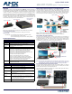
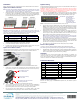
Table Of Contents

© 2016 Harman. All rights reserved. Hydraport, AMX, AV FOR AN IT WORLD, HARMAN, and their respective logos are registered trademarks of
HARMAN. Oracle, Java and any other company or brand name referenced may be trademarks/registered trademarks of their respective
companies.
AMX does not assume responsibility for errors or omissions. AMX also reserves the right to alter specifications without prior notice at any time.
The AMX Warranty and Return Policy and related documents can be viewed/downloaded at www.amx.com.
3000 RESEARCH DRIVE, RICHARDSON, TX 75082 AMX.com | 800.222.0193 | 469.624.8000 | +1.469.624.7400 | fax 469.624.7153
AMX (UK) LTD, AMX by HARMAN - Auster Road, Clifton Moor, York, YO30 4GD United Kingdom • +44 1904-343-100 • www.amx.com/eu/
93-0554-21 REV: A
Last Revised: 3/15/2016
Installation
Refer to the following steps to install the MyTurn Source Select Buttons and Receivers.
MyTurn Source Selector Receiver
Note: The MyTurn Source Selector Wireless Receiver must be installed within 10 meters
(32 ft) of the MyTurn Source Selector Buttons. Care must be taken to minimize
metal obstructions to the wireless signal (i.e., equipment racks).
1. Remove the Phoenix connector from the back of the receiver and wire the outputs
to the Solecis, DVX, or NX/NI Master Controller using the screw down terminals.
Ensure Power and Ground are connected as shown (FIG. 5). Use the AXLINK ports
for Power and Ground if connecting to a Solecis as described in FIG. 3.
Note: When connecting each output (1-8), note the device type, input port, location (ex.
HydraPort Pos-1) on the worksheet below-right for recording this data. It may be needed
when pairing the MyTurn Source Selector Buttons with the wireless receiver ports.
Refer to the wiring chart below for the appropriate wire gauge.
2. Connect the +12V and Ground wire ends to the MyTurn Source Selector Receiver
and GPIO or AxLink plugs first to ensure proper connection.
3. Connect the remaining outputs to the plugs on both ends.
4. Insert the plugs at the Receiver and then the GPIO or AxLink sockets. The green
LED on the rear of the Receiver will light when power is applied.
MyTurn Source Selector Button
The MyTurn Source Selector Button can be installed onto the end of any MyTurn-Ready
cable (FIG. 6). It is then wirelessly paired to the MyTurn Source Selector Receiver.
1. At the source end of the cable, clip the MyTurn Source Selector Button onto the
MyTurn-Ready connector over-mold with the LED over the connector end (FIG. 7).
2. There are short and tall securing clips. The Tall clip is used on the RGB+Stereo
MyTurn-Ready cable due to the bulk of the over-mold. Press the clip into the
MyTurn-Ready cable channel until it clicks over the MyTurn-Ready button.
3. Pair each MyTurn Source Select Button as it is installed. Refer to the install
worksheet f illed out during the MyTurn Source Selector Receiver installation.
MyTurn Pairing
Perform the following steps to pair each MyTurn Source Selector Button with each port
on the MyTurn Source Selector Receiver.
Caution: A receiver will hear every MyTurn Source Select Button within its proximity
(receivers in adjoining conference rooms will likely see each other's TX's but will ignore
any that it is not paired with.) It is the responsibility of the installer to only put one
receiver at a time into pairing mode to avoid inadvertent behavior.
1. Press and hold the Select button on the front of the MyTurn Source Selector
Receiver for approximately 3 seconds. The yellow port LEDs will all flash and Port
1 will blink awaiting the wireless MyTurn Source Selector Button press to pair.
2. Press the MyTurn Source Select Button to pair it with the blinking port or press
Select to select another port to pair with. Upon successful pairing, the selected
LED will turn on solid for one second, and then the LED flashing will advance to the
next output to indicate the device is still in pairing mode. The receiver will pair the
first transmitter it hears when pairing a particular output.
3. Repeat the MyTurn Source Select Button installation and pairing procedure for
each button required. To exit the pairing mode, press the Select button for 3
seconds again. All front yellow LEDs will flash 3 times and then the first output
will be selected. Pairing mode will exit after 2 minutes of no action.
Note: Successive momentary presses of the front panel button on the receiver will
keep the unit in pairing mode, resetting the pairing timeout counter, and advance
the slot assignment to the next output in a round-robin fashion.
4. If the unit has exited pairing mode before all ports are paired, press and hold the
Select button for 3 seconds again to enter the pairing mode and momentarily
press the button multiple times to advance the pairing to restart where the last
port was set. A new pairing will overwrite the prior pairing.
5. Secure the device under the table once all cabling and pairing is complete.
Return to Factory Default
To return a receiver to the factory default settings, perform the following steps:
Note: Returning to factory defaults will wipe any pairing data from the system memory.
1. Hold the SELECT button and apply power. Continue holding the SELECT button for
another 3 seconds. All receiver output status LEDs will simultaneously flash three
times on startup (after being returned to factory settings).
Operation
To operate the MyTurn Source Selector Button after installation is complete, just
connect the cable source end to the presenting device and momentarily push the
MyTurn Source Selector Button. The LED on the button will momentarily flash green.
The device content is now viewable on the main display.
Installation Worksheet
Additional Documentation
Refer to the catalog page on www.amx.com (Dealer Site) for additional product
documentation.
FIG. 5
PHOENIX CONNECTOR WIRING (DVX/NI-CONTROLLER GPIO TO MYTURN RECEIVER)
WIRING GUIDELINES
Wire Size Maximum wiring length Wire Size Maximum wiring length
18 AWG 154.83 feet (47.19 meters) 22 AWG 63.40 feet(19.32 meters)
20 AWG 98.30 feet(29.96 meters) 24 AWG 38.68 feet (11.79 meters)
FIG. 6 MYTURN-READY SOURCE SELECTOR BUTTONS SHOWN MOUNTED ON VARIOUS CABLES
FIG. 7 MYTURN-READY SOURCE SELECTOR BUTTON CLIPPING ONTO CABLE END
RGB+Stereo
HDMI
mDP
DP
USB Type A
Clip installs under cable and latches
MyTurn Button clips into
Channel in MyTurn-Ready
source cable channel
cable over-mold
over the MyTurn Button
FIG. 8 MYTURN SOURCE SELECTOR WIRELESS RECEIVER - SELECT BUTTON
MYTURN RECEIVER DEVICE INPUT
Port Wired to Device Type/Name Port Pair to Cable Type/Location
1
2
3
4
5
6
7
8
Select Button - press momentarily
to switch ports
- press and hold 3 sec
to start pairing
- press and hold 3 sec
during power up to
reset to factory default