instruction manual NetLinx CardFrame, Control Cards, and NetModules NXC, NXF, and NXM Series N e t L i n x C e n t ra l C o n t r o l l e r s a n d C a r d s
AMX Limited Warranty and Disclaimer AMX Corporation warrants its products to be free of defects in material and workmanship under normal use for three (3) years from the date of purchase from AMX Corporation, with the following exceptions: • Electroluminescent and LCD Control Panels are warranted for three (3) years, except for the display and touch overlay components that are warranted for a period of one (1) year.
Software License and Warranty Agreement LICENSE GRANT. AMX grants to Licensee the non-exclusive right to use the AMX Software in the manner described in this License. The AMX Software is licensed, not sold. This license does not grant Licensee the right to create derivative works of the AMX Software. The AMX Software consists of generally available programming and development software, product documentation, sample applications, tools and utilities, and miscellaneous technical information.
Table of Contents Table of Contents NXF CardFrame and NetModules ............................................................................1 NXF CardFrame ................................................................................................................ 1 NXF Cardframe Specifications ......................................................................................... 2 Mounting Master/Hub Cards in an NXF CardFrame ................................................................
Table of Contents NXC-VAI4 Analog Voltage Control Card .............................................................. 29 Specifications .................................................................................................................. 29 Pinouts and Functions..................................................................................................... 30 Channel Assignments .....................................................................................................
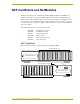
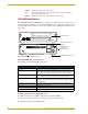
NXF CardFrame and NetModules NXF CardFrame and NetModules NetLinx Control Cards can be installed in the NetLinx (NXF) CardFrame, the NI-4000, or in modules for stand-alone operation. The NXF CardFrame accommodates a NetLinx Master (or Hub) card, up to twelve NetLinx Control cards, and provides a back plane to distribute power and data to/from the cards. The NXF CardFrame provides terminals on the rear panel for connection to the control cards and a system power supply.
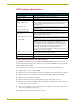
NXF CardFrame and NetModules NXF Cardframe Specifications NXF Cardframe Specifications Power Requirement 12 VDC; varies with installed Control Cards. Dimensions (HWD) 3.5" x 17.0" x 9.6" (8.89 cm x 43.18 cm x 24.38 cm) Weight 9.1 lbs (4.1 kg) Front Panel Components: Master/Hub Card slot Houses the Master or Hub Card. Refer to the NetLinx Master Cards and Modules or NetLinx Hub Cards and Modules instruction manuals for detailed information.
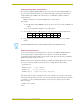
NXF CardFrame and NetModules Setting the CardFrame's starting address The 8-position CardFrame Number DIP switch, located on the rear of the CardFrame (FIG. 1 on page 1), sets the starting address (the device number in the D:P:S specification) for the Control Cards installed in the CardFrame. The address range is 12-3060.
NXF CardFrame and NetModules NUMBER: 16-bit integer represents the device number PORT: 16-bit integer represents the port number (in the range 1 through the number of ports on the Controller or device) SYSTEM: 16-bit integer represents the system number (0 = this system) NXS-NMS NetModules The NXS-NMS NetModules (FG2009-10) accommodate one NetLinx Control Card, and connect to the NetLinx bus via ICSNet connections.
NXF CardFrame and NetModules 3. Place the AC-RK bracket (with the module) in the equipment rack and secure the bracket to the rack. 4. Replace the front faceplate on the module, and attach the translucent plastic cover to the faceplate (if necessary). Installing Control Cards into an NXF CardFrame 1. Remove the magnetic front faceplate/viewing window from the CardFrame. 2. Align the edge of the Control Card with a slot in the CardFrame.
NXF CardFrame and NetModules 6 NXF CardFrame, NetLinx Control Cards, and NetModules
NXC-COM2 Dual COM Port Control Card NXC-COM2 Dual COM Port Control Card The NXC-COM2 Dual COM Port Control Card (FG2022) provides two RS-232, RS-422, or RS-485 control ports and LED feedback for remote sources connected to the NetLinx CardFrame, NI-4000 or NetModule. FIG. 3 shows the COM2 card. ICSNET Status LED LED 1 LED 4 FIG.
NXC-COM2 Dual COM Port Control Card Pinouts and Wiring Configuration NXC-COM2 Pinouts Pin Signal Function NXC-COM2 Wiring Configuration RS-232 RS-422 RS-485 1 GND Signal ground X 2 RXD1 Receive data X 3 TXD1 Transmit data X 4 CTS1 Clear to send X 5 RTS1 Request to send X 6 TX1+ Transmit data 7 TX1- Transmit data X X (strap to pin 9) 8 RX1+ Receive data X X (strap to pin 6) 9 RX1- Receive data X X (strap to pin 7) 10 +12 VDC Power 11 GND Signal ground X 1
NXC-COM2 Dual COM Port Control Card NXC-COM2 Programming Information NXC-COM2 Send_Commands NXC-COM2 Send_Commands Command Description B9MOFF This command works in conjunction with the B9MON command. Disable 9-bit in 232/422/ 455 mode. Syntax: SEND_COMMAND ,"'B9MOFF'" Example: SEND_COMMAND SOMEDEVICE_1,"'B9MOFF'" Sets the port settings on SOMEDEVICE to match the port's configuration settings. B9MON This command works in conjunction with the B9MOFF command. Enable 9-bit in 232/422/455 mode.
NXC-COM2 Dual COM Port Control Card NXC-COM2 Send_Commands (Cont.) Command Description GET BAUD Device sends the response out the Master program port. Get the RS-232/422/485 port’s current communication parameters. Syntax: SEND_COMMAND ,"'GET BAUD'" Example: SEND_COMMAND RS232_1,"'GET BAUD'" Device responds with: ,,,, 485 HSOFF Disable hardware handshaking (default).
NXC-COM2 Dual COM Port Control Card NXC-COM2 Send_Commands (Cont.) Command Description SET BAUD Syntax: Set the RS-232/422/485 port's communication parameters. SEND_COMMAND ,"'SET BAUD ,,, Disable>]'" [485
NXC-COM2 Dual COM Port Control Card NXC-COM2 Send_Commands (Cont.) Command Description XOFF Syntax: Disable software handshaking (default). SEND_COMMAND ,"'XOFF'" Example: SEND_COMMAND RS232_1,"'XOFF'" Disables software handshaking on the RS232_1 device. XON Enable software handshaking. Syntax: SEND_COMMAND ,"'XON'" Example: SEND_COMMAND RS232_1,"'XON'" Enables software handshaking on the RS232_1 device.
NXC-COM2 Dual COM Port Control Card NXC-COM2 Send_String Escape Sequences (Cont.) Command Description 27,20,0 Syntax: Set the RTS hardware SEND_STRING ,"27,20,0" handshake's output to high Example: (> 3V). SEND_STRING RS232_1,"27,20,0" Sets the RTS hardware handshake's output to high on the RS232_1 device. 27,20,1 Set the RTS hardware handshake's output to low/inactive (< 3V).
NXC-COM2 Dual COM Port Control Card 14 NXF CardFrame, NetLinx Control Cards, and NetModules
NXC-I/O10 Input/Output Control Card NXC-I/O10 Input/Output Control Card The NXC-I/O10 Input/Output Control Card (FG2021) provides 10 Input/Output channels and LED feedback. It acts as a logic-level input and responds to switch closures or voltage level (high/ low) changes. The Switch (SW) and Voltage (VO) modes are set with on-board jumpers. FIG. 4 shows the I/O10 card. The I/Os on this card are not dry closure; they are electronic switches that float at 5V when Off.
NXC-I/O10 Input/Output Control Card Pinouts, Signals, and I/O Mode Functions NXC-I/O10 Pinouts, Signals, and I/O Mode Functions Pin Signal SW mode Functions VO mode functions 1 Common Signal ground Common #1 2 I/O #1 Input #1 Input #1 3 Common Signal ground Common #2 4 I/O #2 Input #2 Input #2 5 Common Signal ground Common #3 6 I/O #3 Input #3 Input #3 7 Common Signal ground Common #4 8 I/O #4 Input #4 Input #4 9 Common Signal ground Common #5 10 I/O #5 Input #5 I
NXC-I/O10 Input/Output Control Card Setting the Switch/Voltage Mode Jumpers The NXC-I/O10 responds to switch closures or voltage-level (high/low) changes. Compatible I/O devices include the Power Control Sensor (PCS), tape transports and limit switches. The inputs are set for SW mode (closure) or VO mode as described below. SW (switch) Mode setting (default) Senses switch or relay contact closures or provides a logic-level output.
NXC-I/O10 Input/Output Control Card 18 NXF CardFrame, NetLinx Control Cards, and NetModules
NXC-IRS4 4-Port IR/S Control Card NXC-IRS4 4-Port IR/S Control Card The NXC-IRS4 4-Port IR/S Control Card (FG2023) provides four IR/Serial input control ports with LED status feedback. Each port in the NXC-IRS4 stores programmed commands for IR- or serial-controlled devices. FIG. 5 shows the IRS4 card. FIG.
NXC-IRS4 4-Port IR/S Control Card Pinouts, Signals, and Functions NXC-IRS4 Pinouts, Signals, and Functions Pin Signal Function Pin Signal Function 1 2 GND Signal ground 10 Input #1 Logic input Output #1 IR data 11 Input #2 Logic input 3 4 GND Signal ground 12 Input #3 Logic input Output #2 IR data 13 Input #4 Logic input 5 GND 6 Output #3 Signal ground 14 Power +12 VDC IR data 15 ----------------- no connection 7 GND Signal ground 16 ----------------- no connectio
NXC-IRS4 4-Port IR/S Control Card NXC-IRS4 Send_Commands (Cont.) Command Description CH All channels below 100 are transmitted as two digits. If the IR code for ENTER (function #21) is loaded, an Enter will follow the number. If the channel is greater than or equal to (>=) 100, then IR function 127 or 20 (whichever exists) is generated for the one hundred digit. Uses 'CTON' and 'CTOF' times for pulse times. Send IR pulses for the selected a channel.
NXC-IRS4 4-Port IR/S Control Card NXC-IRS4 Send_Commands (Cont.) Command Description GET MODE The port responds with: ,,. Syntax: Poll the IR/Serial port's configuration parameters and SEND_COMMAND ,"'GET MODE'" report the active mode Example: settings to the device requesting the information.
NXC-IRS4 4-Port IR/S Control Card NXC-IRS4 Send_Commands (Cont.) Command Description PON If at any time the IR sensor input reads that the device is OFF (such as if one turned it off manually at the front panel), IR function 27 (if available) or IR function 9 is automatically generated in an attempt to turn the device back ON. If three attempts fail, the IR port will continue executing commands in the buffer and trying to turn the device On.
NXC-IRS4 4-Port IR/S Control Card NXC-IRS4 Send_Commands (Cont.) Command Description Sets an IR device to link to an input channel for use with 'PON', and 'POF' Sets an IR device to link to an commands. This input channel is used for power sensing (via the PCS). A channelof zero disables the link. input channel for use with 'PON' and 'POF' commands. Syntax: The input channel is used for SEND_COMMAND ,"'SET INPUT LINK '" power sensing (via a PCS). Variable: SET INPUT LINK channel = 1 - 4.
NXC-IRS4 4-Port IR/S Control Card NXC-IRS4 Send_Commands (Cont.) Command Description XCHM Syntax: Changes the IR output pattern for the 'XCH' send command. SEND_COMMAND ,"'XCHM '" Variable: extended channel mode = 0 - 4. Example: SEND_COMMAND IR_1,"'XCHM 3'" Sets the IR_1 device's extended channel command to mode 3. Mode 0 Example (default): [x][x] SEND_COMMAND IR_1,"'XCH 3'" Transmits the IR code as 3-enter.
NXC-IRS4 4-Port IR/S Control Card 26 NXF CardFrame, NetLinx Control Cards, and NetModules
NXC-REL10 Relay Control Card NXC-REL10 Relay Control Card The NXC-REL10 Relay Control Card (FG2020) provides ten relays that support devices that employ simple momentary or latching contact-closure control, with LED feedback. FIG. 6 shows the REL-10 card: NO and NC 3-pin jumpers J1 - J5 NO and NC 3-pin jumpers J6 - J10 FIG.
NXC-REL10 Relay Control Card NXC-REL10 Channel Assignments Channels 1-10 represent relays 1-10. NXC-REL10 Connections/Wiring The NXC-REL10 Control Card has 10 relays that are independently controlled and electrically isolated. The relay contacts are rated for a maximum of 1 A @ 0-24 VAC or 0-28 VDC (resistive). Jumpers located on the Card allow you to select Normally Open (NO) or Normally Closed (NC) contact settings: Normally open (NO) mode setting on jumper pins 1 and 2 (default).
NXC-VAI4 Analog Voltage Control Card NXC-VAI4 Analog Voltage Control Card The NXC-VAI4 Analog Voltage Control Card (FG2025) provides four independent analog-todigital inputs and four independent digital-to-analog outputs, which are controllable over the ICSP network. Each port can be configured for a variety of DC input and output signals. The NXC-VAI4 incorporates the functionality of the AXC-VAI2 and AXC-VRG AXlink cards. FIG. 7 shows the VAI4 card: FIG.
NXC-VAI4 Analog Voltage Control Card NXC-VAI4 Specifications (Cont.) I/O Status LEDs 1-8: (two LEDs per channel) LEDs light to indicate ON status. • 4 yellow LED's (one per channel) light to indicate input signal changes reported to the Master. • 4 red LED's (one per channel) light to indicate output signal changes.
NXC-VAI4 Analog Voltage Control Card Channel Assignments The channel ON/OFF assignments for the NXC-VAI4 are described in the following table. Off = 50% voltage, and all channel assignments are mutually exclusive. NXC-VAI4 Channel Assignments Channel State Function Channel 1 ON While channel 1 is ON, the voltage on Output 1 will ramp up at the "CURRENT OUTPUT 1 RAMP UP TIME" rate. The voltage ramp stops if the maximum is reached. OFF Stops voltage ramping on Output 1 at current value.
NXC-VAI4 Analog Voltage Control Card NXC-VAI4 Channel Assignments (Cont.) Channel State Function Channel 16 ON While channel 16 is ON, the voltage on Output 3 is set to 0% OFF Sets Output 3 voltage to 50%. ON While channel 17 is ON, the voltage on Output 4 is set to 0% OFF Sets Output 4 voltage to 50%. ON While channel 18 is ON, the voltage on Output 1 is set to 75% OFF Sets Output 1 voltage to 50%.
NXC-VAI4 Analog Voltage Control Card NXC-VAI4 Output Level Assignments NXC-VAI4 Output Level Assignments Level Description 1 8 bit field; sets voltage on Output 1 to the value commanded. The range is 0-255. Conflicts with channels 1, 5, 10, 14, 18, 22. 2 8 bit field; sets voltage on Output 2 to the value commanded. The range is 0-255. Conflicts with channels 2, 6, 11, 15, 19, 23. 3 8 bit field; sets voltage on Output 3 to the value commanded. The range is 0-255.
NXC-VAI4 Analog Voltage Control Card NXC-VAI4 Input Level Assignments NXC-VAI4 Input Level Assignments Level Description 1 8 bit field, returns the current output voltage code for Output 1 (range= 0 to 255). 2 8 bit field, returns the current output voltage code for Output 2 (range= 0 to 255). 3 8 bit field, returns the current output voltage code for Output 3 (range= 0 to 255). 4 8 bit field, returns the current output voltage code for Output 4 (range= 0 to 255).
NXC-VAI4 Analog Voltage Control Card NXC-VAI4 Send_Commands (Cont.) Command Description GAS When these variables have been set, and a GL command is in progress, the speed output on Output will be reduced to that specified when the position as read on Output is within the distance specified away from the target position. Sets the slowdown distance and slowdown speed.
NXC-VAI4 Analog Voltage Control Card NXC-VAI4 Send_Commands (Cont.) Command Description GS The change of speed takes place immediately even if a positional change Sets the speed variable to be operation is currently in progress. The voltage output for speed 0 (i.e. when no used for future positional (GL) motion is desired) is at the mid-point between the Min and Max output voltages. The positive speed 127 is the max and negative speed 127 is the commands. min. Other speeds are scaled proportionately.
NXC-VAI4 Analog Voltage Control Card NXC-VAI4 Send_Commands (Cont.) Command Description PE The specified output will then remain proportional to the specified input. Selects which voltage reference (if any) is to be used for scaling of the output voltage. Syntax: SEND_COMMAND ,'P
NXC-VAI4 Analog Voltage Control Card NXC-VAI4 Send_Commands (Cont.) Command Description PN Voltage settings are rounded to the nearest D/A or A/D code. Voltage settings for Outputs are absolute levels and are unaffected by any software scaling functions. Negative voltages are not valid for Input 3. Sets the value of either the minimum output voltage allowed for an output, or the minimum position voltage expected for an input.
NXC-VAI4 Analog Voltage Control Card NXC-VAI4 Send_Commands (Cont.) Command Description PX Voltage settings are rounded to the nearest D/A or A/D code. Voltage settings are absolute levels and are unaffected by any scaling functions. Negative voltages are not valid for Inputs. Sets the value of "I/O MAXIMUM" which is either the maximum output voltage allowed for an Output, or the maximum position voltage expected for an Input.
NXC-VAI4 Analog Voltage Control Card 40 NXF CardFrame, NetLinx Control Cards, and NetModules
NXC-VOL4 Volume Control Card NXC-VOL4 Volume Control Card The NXC-VOL4 Volume Control Card (FG2024) provides four discrete volume control channels with LED feedback. The volume control channels can be programmed for mono or stereo operation, and balanced or unbalanced audio connections. It supports programmable audio levels, audio mute, variable ramp speeds and preset levels.
NXC-VOL4 Volume Control Card NXC-VOL4 Specifications (Cont.) Gain jumpers 1-4 • Unity Maximum Input Level: +10dBm • Pro level to Consumer level conversion (attenuation of +4dBu IN to -10dBu OUT) Maximum Input Level: +10dBm • Consumer level to Pro level conversion (gain of -10dBu IN to +4dBu OUT) Maximum Input Level: +6dBm Connections/wiring Two 10-pin 3.5 mm captive-screw terminals Audio Specifications • Frequency response of 15 Hz - 25 KHz· • THD less than .
NXC-VOL4 Volume Control Card NXC-VOL4 Connections/Wiring The NXC-VOL4 card contains four audio volume control channels. Each line-level channel is isolated from system ground and can be configured for balanced or unbalanced line operation. It supports programmable audio levels, audio mute, variable ramp speeds, and preset levels. Each audio channel's input to output gain ratio is adjustable via the on-board jumpers shown in FIG. 8 on page 41.
NXC-VOL4 Volume Control Card NXC-VOL4 Levels Volume (audio) channels 1 and 2 use levels 1 and 2 respectively. For reading current volume levels and displaying bargraphs see CREATE_LEVEL and SEND_LEVEL .
NXC-VOL4 Volume Control Card Programming Information These NetLinx Send_Commands control the NXC-VOL4. NXC-VOL4 Send_Commands Command Description PL Syntax: Ramps specified (audio) SEND_COMMAND ,'P
ARGENTINA • AUSTRALIA • BELGIUM • BRAZIL • CANADA • CHINA • ENGLAND • FRANCE • GERMANY • GREECE • HONG KONG • INDIA • INDONESIA • ITALY • JAPAN LEBANON • MALAYSIA • MEXICO • NETHERLANDS • NEW ZEALAND • PHILIPPINES • PORTUGAL • RUSSIA • SINGAPORE • SPAIN • SWITZERLAND • THAILAND • TURKEY • USA ATLANTA • BOSTON • CHICAGO • CLEVELAND • DALLAS • DENVER • INDIANAPOLIS • LOS ANGELES • MINNEAPOLIS • PHILADELPHIA • PHOENIX • PORTLAND • SPOKANE • TAMPA 3000 RESEARCH DRIVE, RICHARDSON, TX 75082 USA • 800.222.