Hardware Reference Guide NI-x100 Series NetLinx® Integrated Controllers (NI-2100, NI-3100, NI-4100) NetLinx Integrated Controllers L a s t R e v i s e d : 1 /9 / 2 0 0 9
AMX Limited Warranty and Disclaimer AMX warrants its products to be free of defects in material and workmanship under normal use for three (3) years from the date of purchase from AMX, with the following exceptions: • Electroluminescent and LCD Control Panels are warranted for three (3) years, except for the display and touch overlay components that are warranted for a period of one (1) year.
Table of Contents Table of Contents Introduction ........................................................................................................1 NI-2100 Specifications .............................................................................................. 2 NI-3100 Specifications .............................................................................................. 5 NI-4100 Specifications .............................................................................................
Table of Contents Input/Output (I/O) Port: Connections and Wiring ................................................... 27 IR/Serial Port: Connections and Wiring................................................................... 28 NetLinx Control Card Slot Connector (NI-4100 only).............................................. 28 Ethernet/RJ-45 Port: Connections and Wiring ........................................................ 29 Ethernet LEDs ...............................................................
Introduction Introduction The X100-Series of NetLinx Integrated Master Controllers can both be programmed to control RS-232/422/485, Relay, IR/Serial, and Input/Output devices through the use of both the NetLinx programming language and the NetLinx Studio application version 2.x. Another key feature of this products is the ability to easily access the configuration switches without having to remove a cover plate.
Introduction These NI Controllers use a combination lithium battery and clock crystal package called a Timekeeper. Only one Timekeeper unit is installed within a given NI controller. The battery can be expected to have up to 3 years of usable life under very adverse conditions. Actual life is appreciably longer under normal operating conditions. This calculation is based on storing the unit without power in 50° C (120° F) temperature until battery levels are no longer acceptable.
Introduction NI-2100 Specifications Dimensions (HWD): • 3.47" x 17.00" x 3.47" (8.81 cm x 43.18 cm x 8.82 cm) • 2 rack units high Power Requirement: 700 mA @ 12 VDC Memory: • 64 MB SDRAM Compact Flash: 128 MB or more - Upgradeable (see Other AMX Equipment) • 1 MB Non-volatile (NV) SRAM Note: AMX may increase Flash size at any time in response to market availability (refer to product’s online catalog page for current Compact Flash size provided). Weight: 4.50 lbs (2.
Introduction NI-2100 Specifications (Cont.) Rear Panel Components (Cont.): • IR/Serial (Ports 5 - 8): 4 IR/Serial control ports support high-frequency carriers of up to 1.142 MHz with each output being capable of two electrical formats: IR or Serial. • 4 IR/Serial data signals can be generated simultaneously. • IR ports support data mode (at limited baud rates and wiring distances). • Program Port: RS-232 DB9 connector (male) can be connected to a DB9 port on a PC.
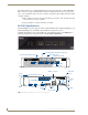
Introduction NI-3100 Specifications The NI-3100 (FIG. 3) provides support for 7 RS-232/RS-422/RS-485 Ports, 8 IR/Serial Output ports, 8 Digital Input/Output ports, and 8 Relays. The NI-3100 can be upgraded to provide one ICSHub and two ICSNet ports by either installing the optional ICSNet daughter card (FG2105-10) or purchasing this upgrade as an included feature of the NI3100 Kit (FG2105-15). FIG.
Introduction NI-3100 Specifications Dimensions (HWD): • 3.47" x 17.00" x 3.47" (8.81 cm x 43.18 cm x 8.82 cm) Power Requirement: 900 mA @ 12 VDC Memory: • 64 MB SDRAM Compact Flash: 128 MB or more • 2 rack units high • 1 MB Non-volatile (NV) SRAM • AMX may increase Flash size at any time in response to market availability • Upgradeable - see Other AMX Equipment Weight: 4.55 lbs (2.
Introduction NI-3100 Specifications (Cont.) Rear Panel Components (Cont.): • IR/Serial (Ports 9 - 16): 8 IR/Serial control ports support high-frequency carriers of up to 1.142 MHz with each output being capable of two electrical formats: IR or Serial. • 8 IR/Serial data signals can be generated simultaneously. • IR ports support data mode (at limited baud rates and wiring distances). • Program Port: RS-232 DB9 connector (male) can be connected to a DB9 port on a PC.
Introduction NI-4100 Specifications The NI-4100 (FIG. 5) is geared toward those advanced control and automation requirements associated with most complex commercial and residential installations. The NI-4100 provides support for up to 4 NetLinx control cards (such as NXC-COM2, NXC-IRS4, etc.), 7 RS-232/RS-422/RS-485 Ports, 8 IR/Serial Output ports, 8 Digital Input/Output ports, and 8 Relays. The NI-4100’s on-board Master also provides the ability to update installed control card firmware. FIG.
Introduction NI-4100 Specifications Dimensions (HWD): • 5.21" x 17.00" x 9.60" (13.23 cm x 43.18 cm x 24.27 cm) • 3 rack units high Power Requirement: • 900 mA @ 12 VDC Memory: • 64 MB SDRAM Compact Flash: 128 MB or more • 1 MB Non-volatile (NV) SRAM • AMX may increase Flash size at any time in response to market availability • Upgradeable - see Other AMX Equipment Weight: 9.15 lbs (4.
Introduction NI-4100 Specifications (Cont.) Rear Panel Components (Cont.): • Program Port: RS-232 DB9 connector (male) can be connected to a DB9 port on a PC. This connector can be used with serial and NetLinx programming commands, as well as other DB9 capable devices, to both upload/download information from the NetLinx Studio program. • Configuration DIPSwitch: Sets the communication parameters for the Program port (see Baud Rate Settings).
Introduction Related Documents For information on using the on-board Web Console, as well as NetLinx send commands and terminal communications to configure the NI Controllers, refer to the NetLinx Integrated Controller WebConsole & Programming Guide. All product documentation is available to view or download from www.amx.com.
Introduction 12 NI-2100, NI-3100, NI-4100 Hardware Reference Guide
Installation and Upgrading Installation and Upgrading Installing NetLinx Control Cards (NI-4100 Only) NetLinx Cards can be installed into the front card slots. The cards mount horizontally through the card slot openings on the front of the enclosure. 1. Discharge the static electricity from your body, by touching a grounded object. 2. Remove the three screws by turning them in a counter-clockwise direction and then remove the faceplate (FIG. 7). Thumbscrews NXC Card Slot faceplate FIG.
Installation and Upgrading If the cards do not appear in the NetLinx Studio’s Workspace window for the selected Master System number: give the system time to detect the inserted cards (and refresh the system) and/or cycle power to the unit. Setting the NetLinx Control Card Addresses (NI-4100 Only) The 8-position CardFrame Number DIP switch (located on the rear of the NI-4100) sets the starting address (the device number in the D:P:S specification) for the Control Cards installed in the CardFrame.
Installation and Upgrading NUMBER:PORT:SYSTEM where: NUMBER: 16-bit integer represents the device number PORT: 16-bit integer represents the port number (in the range 1 through the number of ports on the Controller or device) SYSTEM: 16-bit integer represents the system number (0 = this system) Removing NetLinx Control Cards (NI-4100 Only) To install NetLinx Control Card: 1.
Installation and Upgrading Chassis housing screws (top) - 6 on top - sides vary per model Mounting Brackets Compact Flash Compact Flash insert location Chassis housing screws (side) - 4 on each side of the NI-4100 - 3 on each side of the NI-3100/2100 NXC Card Slot faceplate NXC Card Slots FIG. 9 Location of the Compact Flash within a sample Integrated Controller 3. Carefully pull-up and remove the housing up and away from the Controller to expose the internal circuit board (FIG. 9). 4.
Installation and Upgrading Under-side groove located below Card Removal Grooves Insert with arrow facing towards the connector pins FIG. 10 Removing the Compact Flash card 7. To complete the upgrade process, close and re-secure the Integrated Controller enclosure using the procedures outlined in the following section. Any new internal card upgrade is detected by the Controller only after power is cycled.
Installation and Upgrading Install screws Bracket Rack Mounting Holes FIG. 11 Mounting Integrated Controller into an equipment rack 3. Thread the cables through the opening in the equipment rack. Allow for enough slack in the cables to accommodate for movement during the installation process. 4. Reconnect all cables to their appropriate source/terminal locations. Refer to theConnections and Wiring section on page 19 for more detailed wiring and connection information.
Connections and Wiring Connections and Wiring Setting the Configuration DIP Switch (for the Program Port) Prior to installing the Controller, use the Configuration DIP switch to set the baud rate used by the Program port for communication. The Configuration DIP switch is located on the front of the Integrated Controllers.
Connections and Wiring Think of the PRD Mode (On) equating to a PC’s SAFE Mode setting. This mode allows a user to continue powering a unit, update the firmware, and download a new program while circumventing any problems with a currently downloaded program. Power must be cycled to the unit after activating/deactivating this mode on the Program Port DIP switch #1. Working With the Configuration DIP Switch 1.
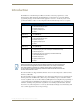
Connections and Wiring Modes and Front Panel LED Blink Patterns The following table lists the modes and blink patterns for the front panel LEDs associated with each mode. These patterns are not evident until after the unit is powered. Modes and LED Blink Patterns LEDs and Blink Patterns STATUS (green) OUTPUT INPUT (red) (yellow) Mode Description OS Start Starting the operating system (OS). On On On Boot On-board Master is booting.
Connections and Wiring AXlink Port and LED All NI units have an AXlink port and adjacent status LED (FIG. 12). This port allows the NI to support AMX Legacy AXlink devices such as G3 touch panels (ex: CP4/A) and PosiTrack Pilot devices. A green LED shows AXlink data activity. When the AXlink port is operating normally, blink patterns include: Off - No power, or the controller is not functioning properly 1 blink per second - Normal operation. 3 blinks per second - AXlink bus error.
Connections and Wiring Preparing Captive Wires You will need a wire stripper and flat-blade screwdriver to prepare and connect the captive wires. Never pre-tin wires for compression-type connections. 1. Strip 0.25 inch (6.35 mm) of insulation off all wires. 2. Insert each wire into the appropriate opening on the connector (according to the wiring diagrams and connector types described in this section). 3. Tighten the screws to secure the wire in the connector.
Connections and Wiring Using the 4-pin Mini-Phoenix Connector For Data With External Power To use the 4-pin 3.5 mm mini-Phoenix (female) captive-wire connector for data communication and power transfer, the incoming PWR and GND cable from the 12 VDC-compliant power supply must be connected to the AXlink cable connector going to the Integrated Controller. FIG. 15 shows the wiring diagram. Always use a local power supply to power the Integrated Controller unit.
Connections and Wiring The table below provides information about the connector pins, signal types, and signal functions.
Connections and Wiring 1 2 3 4 5 6 7 8 1 2 3 4 5 6 7 8 (female) (male) RJ-45 connector - pin configurations Unlike the ICSNet ports, the ICSHub connections require a specific polarity. The IN/OUT configuration, on the hub ports, was implemented to use the same cables as ICSNet, but these ports need TX and RX crossed. You must connect an OUT to an IN, or an IN to an OUT port. This is done simply to keep the polarity straight. The Hub bus is still a bus. All Hub connections are bi-directional.
Connections and Wiring NI-4100/NI-3100 relay connector configuration (Port 8) NI-2100 relay connector configuration (Port 4) FIG. 17 RELAY connector (male) Input/Output (I/O) Port: Connections and Wiring The I/O port responds to either switch closures, voltage level (high/low) changes, or it can be used for logic-level outputs. NI-2100 I/O connector configuration (Port 9) NI-4100/NI-3100 I/O connector configuration (Port 17) FIG.
Connections and Wiring IR/Serial Port: Connections and Wiring You can connect up to eight IR- or Serial-controllable devices to the IR/Serial connectors on the rear of the NI-4100 and NI-3100 and up to four on the NI-2100 (FIG. 19). These connectors accept an IR Emitter (CC-NIRC) that mounts onto the device's IR window, or a miniplug (CC-NSER) that connects to the device's control jack. You can also connect a data 0 - 5 VDC device. These units come with two CC-NIRC IR Emitters (FG10-000-11).
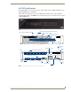
Connections and Wiring Ethernet/RJ-45 Port: Connections and Wiring NI-x100 Controllers feature an Auto MDI/MDI-X Ethernet port. This provides the option of using either a standard (straight through), or a crossover Ethernet cable to communicate with a PC - both cable types will work. The following table lists the pinouts, signals, and pairing for the Ethernet connector.
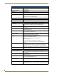
Connections and Wiring Ethernet Ports Used By the Integrated Controller Ethernet Port Descriptions Port type Description Standard Port # FTP The on-board Master has a built-in FTP server. 21/20 (TCP) SSH The SSH port functions using the same interface as Telnet but over a 22 (TCP) secure shell where it uses SSL as a mechanism to configure and diagnose a NetLinx system. This port value is used for secure Telnet communication. Note: SSH version 2 is only supported.
Connections and Wiring NI-2100, NI-3100, NI-4100 Hardware Reference Guide 31
AMX. All rights reserved. AMX and the AMX logo are registered trademarks of AMX. AMX reserves the right to alter specifications without notice at any time. ©2009 1/2009 It’s Your World - Take Control™ 3000 RESEARCH DRIVE, RICHARDSON, TX 75082 USA • 800.222.0193 • 469.624.8000 • 469-624-7153 fax • 800.932.6993 technical support • www.amx.