
Corporation NetLinx Integrated Controllers Hardware Reference Guide


Connections and Wiring
28
NI-2100, NI-3100, NI-4100 Hardware Reference Guide
IR/Serial Port: Connections and Wiring
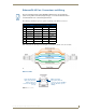
You can connect up to eight IR- or Serial-controllable devices to the IR/Serial connectors on the rear of
the NI-4100 and NI-3100 and up to four on the NI-2100 (FIG. 19).
These connectors accept an IR Emitter (CC-NIRC) that mounts onto the device's IR window, or a mini-
plug (CC-NSER) that connects to the device's control jack. You can also connect a data 0 - 5 VDC
device.
These units come with two CC-NIRC IR Emitters (FG10-000-11).
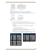
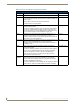
The IR/Serial connector wiring specifications are listed in the following table.
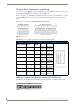
NetLinx Control Card Slot Connector (NI-4100 only)
FIG. 20 shows the 20-pin (male) connector that provides connection to the NetLinx Control Cards.
FIG. 19 IR/SERIAL (male)
IR/Serial Connector Wiring Specifications (per Port)
Number of
IR connections
NI-4100/3100
Port #
NI-2100
Port #
Signal Function
1 9 5 GND (-)
Signal 1 (+)
Signal GND
IR/Serial data
2 10 6 GND (-)
Signal 2 (+)
Signal GND
IR/Serial data
3 11 7 GND (-)
Signal 3 (+)
Signal GND
IR/Serial data
4 12 8 GND (-)
Signal 4 (+)
Signal GND
IR/Serial data
5 13 N/A GND (-)
Signal 5 (+)
Signal GND
IR/Serial data
6 14 N/A GND (-)
Signal 6 (+)
Signal GND
IR/Serial data
7 15 N/A GND (-)
Signal 7 (+)
Signal GND
IR/Serial data
8 16 N/A GND (-)
Signal 8 (+)
Signal GND
IR/Serial data
FIG. 20
NetLinx Control Card 20-pin connector
NI-4100/NI-3100 IR/Serial connector
configuration (Port 9-16)
NI-2100 IR/Serial connector
configuration (Port 5-8)
12 3 45 6 78
12 3 45 6 78
1820 19 15
17
16 610
SLOT 1
11
13
12
987
5
4
3
2114