Hardware Reference Guide NI-700/900 NetLinx Integrated Controllers NetLinx Integrated Controllers Last Revised: 5/13/2008
AMX Limited Warranty and Disclaimer This Limited Warranty and Disclaimer extends only to products purchased directly from AMX or an AMX Authorized Partner which include AMX Dealers, Distributors, VIP’s or other AMX authorized entity.
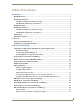
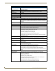
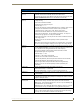
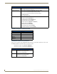
Table of Contents Table of Contents Introduction ........................................................................................................1 NI-700 Overview....................................................................................................... 1 NI-700 Specifications ................................................................................................ 1 NI-700 Port Assignment And Functionality .....................................................................
Table of Contents ii NI-700 & NI-900 Hardware Reference Guide
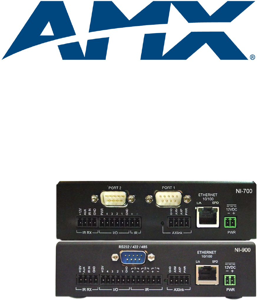
Introduction Introduction NI-700 Overview The NI-700 NetLinx Integrated Master Controller can be programmed to control RS-232/422/485, IR/ Serial, and Input/Output devices through the use of both the NetLinx programming language and the NetLinx Studio application (version 2.4 or higher). Another key feature of this product is the ability to easily access the configuration switches without having to remove a cover plate.
Introduction NI-700 Specifications Dimensions (HWD): • 1.58" x 5.54" x 5.12" (4.01 cm x 14.10 cm x 13.00 cm) Power Requirements: • 280 mA @ 12 VDC Memory: See the NI-700 On-Board Memory Specifications section on page 4. Microprocessor: • 304 MIPS Weight: • 1.30 lbs (0.
Introduction NI-700 Specifications (Cont.) Rear Panel Components (Cont.): IR RX (Port 5) • 4-pin 3.5 mm mini-Phoenix port is used to connect one or more (8 maximum) IRX-SM+ swivel mount or IRX-DM+ Decora mount IR receivers. • The IR RX port functions using AMX IR codes (38 KHz and 455 KHz) and works ONLY with AMX IR Receivers such as the IRX-DM+ and IRX-SM+. Digital I/O (Port 4) • Four-channel binary I/O port for contact closure with each input being capable of voltage sensing.
Introduction NI-700 Specifications (Cont.) Operating Environment: • Operating Temperature: 0° C (32° F) to 50° C (122° F) • Operating Humidity: 20% - 85% RH Included Accessories: • 2-pin 3.5 mm mini-Phoenix female PWR connector (41-5025) • 4-pin 3.5 mm mini-Phoenix female connector (41-5047) • 6-pin 3.
Introduction NI-900 Overview The NI-900 is the first NetLinx device to be Duet-compatible straight out of the box. Duet is a dual-interpreter firmware platform from AMX which combines the proven reliability and power of NetLinx with the extensive capabilities of the Java®2 MicroEdition (J2ME) platform.
Introduction NI-900 Specifications Dimensions (HWD): • 1.58" x 5.54" x 5.12" (4.01 cm x 14.10 cm x 13.00 cm) Power Requirements: • 300 mA @ 12 VDC Memory: See the NI-900 On-Board Memory Specifications section on page 9. Microprocessor: • 304 MIPS Weight: • 1.30 lbs (0.
Introduction NI-900 Specifications (Cont.) Rear Panel Components (Cont.): IR RX (Port 6) • 4-pin 3.5 mm mini-Phoenix port is used to connect one or more (8 maximum) IRX-SM+ swivel mount or IRX-DM+ Decora mount IR receivers. • The IR RX port functions using AMX IR codes (38 KHz and 455 KHz) and works ONLY with AMX IR Receivers such as the IRX-DM+ and IRX-SM+. Digital I/O (Port 5) • Four-channel binary I/O port for contact closure with each input being capable of voltage sensing.
Introduction NI-900 Specifications (Cont.) Rear Panel Components (Cont.): • Ethernet Port: RJ-45 port for 10/100 Mbps communication. LEDs show communication activity, connection status, speeds, and mode information: Ethernet Link/ Activity LED SPD (speed) - Yellow LED lights On when the connection speed is 100 Mbps and turns Off when the speed is 10 Mbps.
Introduction NI-900 On-Board Memory Specifications There are two variations on the NI-900, with different memory specifications. The latest version of the NI-900 has double the on-board memory of previous versions.
Introduction 10 NI-700 & NI-900 Hardware Reference Guide
Installation Installation Device:Port:System (D:P:S) A device is any hardware component that can be connected to an AXlink or ICSNet bus. Each device must be assigned a unique number to locate that device on the bus. The NetLinx programming language allows numbers in the range 1-32,767 for ICSNet (255 for AXlink). Only the Device value can be set through the DIP switch settings mentioned above. NetLinx requires a Device:Port:System (D:P:S) specification.
Installation To prevent repetition of the installation, test the incoming wiring by connecting the Controller’s connectors to their terminal locations and applying power. Verify that the unit is receiving power and functioning properly. Disconnect the terminal end of the power cable from the connected 12 VDC-compliant power supply. 6. Align the ends of the AC-RK with the screw openings along the sides of the equipment rack. 7.
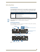
Connections and Wiring Connections and Wiring Setting the Configuration DIP Switch (for the Program Port) Prior to installing the Controller, use the Configuration DIP switch to set the baud rate used by the Program port for communication. The Configuration DIP switch is located on the front of the Integrated Controllers.
Connections and Wiring Think of the PRD Mode (On) equating to a PC’s SAFE Mode setting. This mode allows a user to continue powering a unit, update the firmware, and download a new program while circumventing any problems with a currently downloaded program. Power must be cycled to the unit after activating/deactivating this mode on the Program Port DIP switch #1. Working With the Configuration DIP Switch 1.
Connections and Wiring Modes and Front Panel LED Blink Patterns The following table lists the modes and blink patterns for the front panel LEDs associated with each mode. These patterns are not evident until after the unit is powered. Modes and LED Blink Patterns LEDs and Blink Patterns STATUS (green) OUTPUT INPUT (red) (yellow) Mode Description OS Start Starting the operating system (OS). On On On Boot On-board Master is booting.
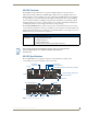
Connections and Wiring NI-700 NI-900 FIG. 1 AXlink connector and LED The AXlink port can be used to supply power to downstream AXlink-compatible devices as long as both the power required is LESS THAN 2 Amps total and the external power supply feeding the NI unit has the necessary power capability. Wiring Guidelines The Integrated Controllers use a 12 VDC-compliant power supply to provide power to the Controller through the rear 2-pin 3.5 mm mini-Phoenix PWR connector.
Connections and Wiring Wiring A Power Connection To use the 2-pin 3.5 mm mini-Phoenix connector with a 12 VDC-compliant power supply, the incoming PWR and GND cables from the external source must be connected to their corresponding locations on connector (FIG. 2). 1. Insert the PWR and GND wires on the terminal end of the 2-pin 3.5 mm mini-Phoenix cable. Match the wiring locations of the +/- on both the power supply and the terminal connector. 2. Tighten the clamp to secure the two wires.
Connections and Wiring Using the 4-pin Mini-Phoenix Connector For Data With External Power To use the 4-pin 3.5 mm mini-Phoenix (female) captive-wire connector for data communication and power transfer, the incoming PWR and GND cable from the 12 VDC-compliant power supply must be connected to the AXlink cable connector going to the Integrated Controller. FIG. 4 shows the wiring diagram. Always use a local power supply to power the Integrated Controller unit.
Connections and Wiring The table below provides information about the connector pins, signal types, and signal functions. This table’s wiring specifications are applicable to the rear RS-232/422/485 Device Port connectors on the: NI-700 (Ports 1 & 2) and NI-900 (Port 1).
Connections and Wiring Input/Output (I/O) Port: Connections and Wiring The I/O port responds to either switch closures, voltage level (high/low) changes, or it can be used for logic-level outputs. You can connect up to four devices to the NI-700 or NI-900 (FIG. 7). Port 4 on the NI-700 Port 5 on the NI-900 FIG. 7 INPUT/OUTPUT connector (male) A contact closure between the GND and an I/O port is detected as a Push. When used for voltage inputs, the I/O port detects a low signal (0 - 1.
Connections and Wiring IR/Serial Port: Connections and Wiring You can connect only one IR- or Serial-controllable device to the IR/Serial connectors on the rear of the NI-700 (FIG. 8) but you can connect up to three IR- or Serial-controllable devices to the rear of the NI-900. These connectors accept an IR Emitter (CC-NIRC) that mounts onto the device's IR window, or a mini-plug (CC-NSER) that connects to the device's control jack. You can also connect a data 0 - 5 VDC device.
Connections and Wiring FIG. 9 diagrams the RJ-45 pinouts and signals for the Ethernet RJ-45 connector and cable. FIG. 9 RJ-45 wiring diagram Ethernet LEDs L/A - Link/Activity LED lights (green) when the Ethernet cables are connected and terminated correctly. SPD - Speed LED lights (yellow) when the connection speed is 100 Mbps and turns Off when speed is 10 Mbps. FIG.
Connections and Wiring Ethernet Ports Used By the Integrated Controller Ethernet Port Descriptions Port type Description Standard Port # FTP The on-board Master has a built-in FTP server. 21/20 (TCP) SSH The SSH port functions using the same interface as Telnet but over a 22 (TCP) secure shell where it uses SSL as a mechanism to configure and diagnose a NetLinx system. This port value is used for secure Telnet communication. Note: SSH version 2 is only supported.
Connections and Wiring 24 NI-700 & NI-900 Hardware Reference Guide
Connections and Wiring NI-700 & NI-900 Hardware Reference Guide 25
AMX. All rights reserved. AMX and the AMX logo are registered trademarks of AMX. AMX reserves the right to alter specifications without notice at any time. ©2008 5/08 It’s Your World - Take Control™ 3000 RESEARCH DRIVE, RICHARDSON, TX 75082 USA • 800.222.0193 • 469.624.8000 • 469-624-7153 fax • 800.932.6993 technical support • www.amx.