
Specifications


Table Of Contents
Quick Start Guide
MSD-431-L 4.3” Modero S Series
®
Wall Mount Touch Panel
Overview
The Modero S Series
®
is a touch panel family sophisticated enough for room
control yet priced right for the most cost sensitive installations, including small
huddle spaces and dedicated room scheduling. The smallest of our Modero S
Series wall mount touch panels, the MSD-431-L 4.3” Wall/Flush Mount Touch
Panel (FG2265-03) still features the advanced technology empowering users to
conduct seamless meetings including VoIP, brilliant 24-bit color depth, PoE
connectivity, and streaming video.
Product Specifications
Note: Optimal performance requires use of one of the following AMX PoE power
supplies (not included):
• PS-POE-AF-TC, PoE Injector, 802.3AF Compliant (FG423-83)
• NXA-ENET8-2POE, Gigabit PoE Ethernet Switch (FG2178-63)
Note: AMX does not support the use of non-AMX power supplies.
Note: For more information on installation and configuration, as well as
complete specifications on this device, please refer to the MSD-431-L/MST-431
Operation/Reference Guide, available at www.amx.com.
Panel Connectors and Wiring
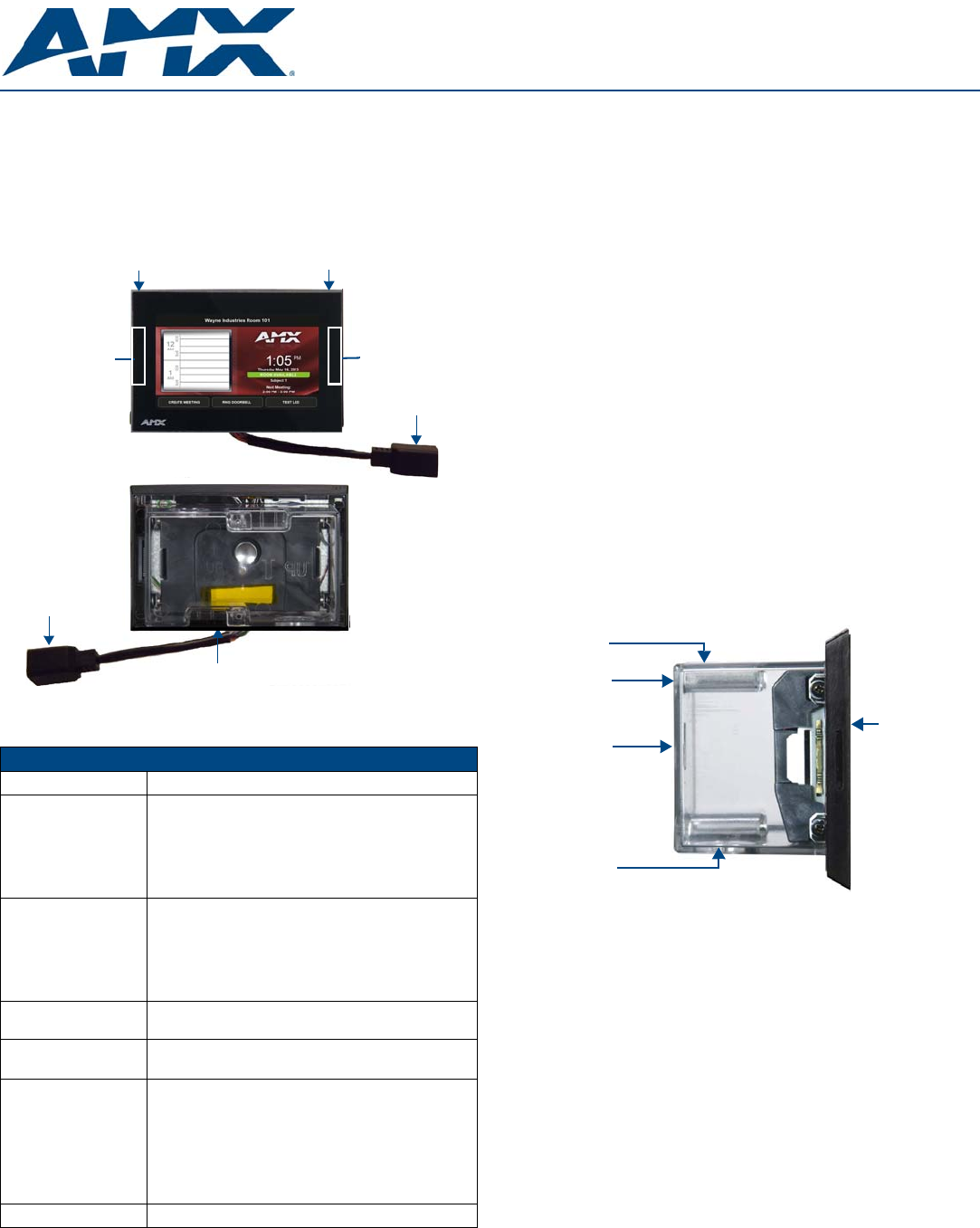
FIG. 1 shows the connectors located on the back of the MSD-431-L.
Power for the MSD-431-L via Power Over Ethernet
Power for the MSD-431-L is supplied via Power Over Ethernet (PoE), utilizing an
AMX-certified PoE injector such as the PS-POE-AF-TC PoE Injector
(FG423-83) or other approved AMX PoE power source. The incoming Ethernet
cable should be connected to the RJ-45 port on the MSD-431-L.
Note: The Micro A/B USB port is used only for firmware uploads, as it is
inaccessible when the device is installed within its back box.
Installing the MSD-431-L
The MSD-431-L can be installed either directly into a solid surface environment,
using either solid surface screws or the included locking tabs for different
mounting options. For more information, please refer to the MSD-431-L/MST-
431 Operation/Reference Guide, available at www.amx.com.
The MSD-431-L is contained within a clear outer housing known as the back
box. This back box is removed when installing the device into a wall or into a
Rough-In Box.
Installing the MSD-431-L into a wall
The back box (FIG. 2) is designed to attach the panel to most standard wall and
solid surface materials. This back box has two locking tabs (one on the top and
one at the bottom) to help lock the back box to the wall. These locking tabs are
only extended AFTER the back box is inserted into the wall. Using the locking
tabs is highly recommended for standard mounting surfaces such as walls. For
thin walls and solid surfaces, use #4 mounting screws (not included).
WARNING: When installing the back box, make sure that the assembly is in the
correct position and in the correct place. Once the locking tabs are extended
and locked into place, removing the back box may be difficult without having
access to the back of the wall or causing damage to the wall.
Note: In order to guarantee a stable installation of the MSD-431-L, the thickness
of the wall material must be a minimum of .50 inches (1.27cm) and a maximum
of .875 inches (2.22cm). The surface should also be smooth and flat.
WARNING: The maximum recommended torque to screw in the locking tabs on
the plastic back box is 5 IN-LB [56 N-CM]. Applying excessive torque while
tightening the tab screws, such as with powered screwdrivers, can strip out the
locking tabs or damage the plastic back box.
1. After ensuring proper placement, cut out the mounting surface. Use the
included mounting template (68-2265-01) or refer to the dimensions in the
MSD-431-L/MST-431 Operation/Reference Guide, available from
www.amx.com, for more information.
CAUTION: Making sure the actual cutout opening is slightly smaller than the
provided dimensions is highly recommended. This action provides the installer
with a margin for error if the opening needs to be expanded. Too little wall
material removed is always better than too much.
2. Remove either the top or the bottom knockout from the back box,
depending upon the required installation. Thread the incoming wiring
through the hole in the rear of the back box.
FIG. 1 MSD-431-L
MSD-431-L Specifications
Power: PoE (Power over Ethernet), 802.3af, class 2
Power Consumption: • Maximum: 5W
• Typical: 3W
• Standby: 2W
• Shutdown: 0.6W
• Startup Inrush Current: Not Applicable due to PoE
standard
Operating Environment: • Operating Temperature: 32° F to 104° F (0° C to 40° C)
• Storage Temperature: 4° F to 140° F (-20° C to 60° C)
• Humidity Operating: 20% to 85% RH
• Humidity Storage: 5% to 85% RH
• Power (“Heat”) Dissipation: 13.6 BTU/hr,
Standby: 6.8 BTU/hr
Dimensions (HWD):
With Back Box: 3.42” x 5.05” x 2.30”
(87 mm x 128 mm x 58 mm)
Weight:
• Without Back Box: 0.50 lbs (0.22 Kg)
• With Back Box: 0.65 lbs (0.29 Kg)
Certifications: • UL
• FCC Part 15 Class B
• C-Tick CISPR 22 Class B
• CE EN 55022 Class B and EN 55024
• CE EN 60950-1
• IC CISPR 22 Class B
• VCCI CISPR 22 Class B
• RoHS/WEEE compliant
Included Accessories: • MSD-431-L Wall Mounting Template (68-2265-01)
Microphone
(Front)
(Rear)
RJ-45
Port
RJ-45
Port
Sleep Button
Micro A/B
USB Port
Right LED
Left LED
FIG. 2 MSD-431-L Back Box (Side View)
Knockout
MSD-431-L
Back
Box
Locking
Tab
Knockout