Operation/Reference Guide NetLinx® Cardframe, Control Cards, and NetModules NXC, NXF, and NXM Series Central Controllers Last Revised: 10/24/2013
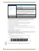
AMX Limited Warranty and Disclaimer This Limited Warranty and Disclaimer extends only to products purchased directly from AMX or an AMX Authorized Partner which include AMX Dealers, Distributors, VIP’s or other AMX authorized entity.
Table of Contents Table of Contents NXF CardFrame and NetModules ......................................................................1 Overview .................................................................................................................. 1 NXF CardFrame ........................................................................................................ 1 NXF Cardframe Specifications .................................................................................
Table of Contents NXC-I/O10 Input/Output Control Card ............................................................11 Specifications .......................................................................................................... 11 Pinouts, Signals, and I/O Mode Functions .............................................................. 12 NXC-I/O10 Channel Assignments ........................................................................... 12 Setting the Switch/Voltage Mode Jumpers .............
Table of Contents DEFAULT ALL......................................................................................................................... GAS ........................................................................................................................................ GD.......................................................................................................................................... GL............................................................................
Table of Contents iv NetLinx Cardframe, Control Cards, and NetModules - Operation Reference Guide
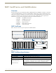
NXF CardFrame and NetModules NXF CardFrame and NetModules Overview NetLinx Control Cards can be installed in the NetLinx® (NXF) CardFrame, the NI-4000, or in modules for stand-alone operation. The NXF CardFrame accommodates a NetLinx Master (or Hub) card, up to twelve NetLinx Control cards, and provides a back plane to distribute power and data to/from the cards. The NXF CardFrame provides terminals on the rear panel for connection to the control cards and a system power supply.
NXF CardFrame and NetModules NXF Cardframe Specifications (Cont.) Rear Panel Components: Card slots Twelve 20-pin black (male) connectors and mating 3.5 mm captive-screw terminals supplied with Control Cards. Control Card connectors (1-12) 20-pin black (male) connectors that connect the Control Cards and external equipment to the CardFrame. +12 VDC PWR 2-pin green (male) connector for connecting a 12 VDC power supply.
NXF CardFrame and NetModules Device:Port:System (D:P:S) A device is any hardware component that can be connected to an AXlink or ICSNet bus. Each device must be assigned a unique number to locate that device on the bus. The NetLinx programming language allows numbers in the range 032,767. Device 0 refers to the local Master; numbers greater than 32,767 are reserved. NetLinx requires a Device:Port:System (D:P:S) specification.
NXF CardFrame and NetModules NXS-NMS NetModules Specifications (Cont.) ICSNet RJ-45 connectors Receives power and data from a NetLinx Master/Hub ICSNet Port. An ICSNet port on a NetLinx Master or Hub supplies up to 500 mA at 12 V for module power. 12 VDC power supply connectors Two parallel male 2-pin (green) parallel connectors for 12 VDC power.
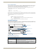
NXC-COM2 Dual COM Port Control Card NXC-COM2 Dual COM Port Control Card The NXC-COM2 Dual COM Port Control Card (FG2022) provides two RS-232, RS-422, or RS-485 control ports and LED feedback for remote sources connected to the NetLinx CardFrame, NI-4000 or NetModule. FIG. 3 shows the COM2 card. ICSNET Status LED LED 1 LED 4 FIG.
NXC-COM2 Dual COM Port Control Card Pinouts and Wiring Configuration NXC-COM2 Pinouts NXC-COM2 Wiring Configuration Pin Signal Function RS-232 RS-422 1 GND Signal ground X X RS-485 2 RXD1 Receive data X 3 TXD1 Transmit data X 4 CTS1 Clear to send X 5 RTS1 Request to send X 6 TX1+ Transmit data X X (strap to pin 8) 7 TX1- Transmit data X X (strap to pin 9) 8 RX1+ Receive data X X (strap to pin 6) 9 RX1- Receive data X X (strap to pin 7) 10 +12 VDC Power
NXC-COM2 Dual COM Port Control Card NXC-COM2 Send_Commands (Cont.) Command Description CHARD Set the delay time between all transmitted characters to the value specified (in 100 microsecond increments). Syntax: SEND_COMMAND ,"'CHARD-
NXC-COM2 Dual COM Port Control Card NXC-COM2 Send_Commands (Cont.) Command Description HSON Enable RTS (ready-to-send) and CTS (clear-to-send) hardware handshaking. Syntax: SEND_COMMAND ,"'HSON'" Example: SEND_COMMAND RS232_1,"'HSON'" Enables hardware handshaking on the RS232_1 device. RXCLR Clear all characters in the receive buffer waiting to be sent to the Master.
NXC-COM2 Dual COM Port Control Card NXC-COM2 Send_Commands (Cont.) Command Description TSET BAUD Temporarily set the RS-232/422/485 port's communication parameters for a device. Works the same as SET BAUD, except that the changes are not permanent, and the previous values will be restored if the power is cycled on the device.
NXC-COM2 Dual COM Port Control Card NXC-COM2 Send_String Escape Sequences (Cont.) Command Description 27,18,0 Clear the ninth data bit by setting it to 0 on all character transmissions. Used in conjunction with the 'B9MON' command. Syntax: SEND_STRING ,"27,18,0" Example: SEND_STRING RS232_1,"27,18,0" Sets the RS232_1 device's ninth data bit to 0 on all character transmissions. 27,18,1 Set the ninth data bit to 1 for all subsequent characters to be transmitted.
NXC-I/O10 Input/Output Control Card NXC-I/O10 Input/Output Control Card The NXC-I/O10 Input/Output Control Card (FG2021) provides 10 Input/Output channels and LED feedback. It acts as a logic-level input and responds to switch closures or voltage level (high/ low) changes. The Switch (SW) and Voltage (VO) modes are set with on-board jumpers. FIG. 4 shows the I/O10 card. The I/Os on this card are not dry closure; they are electronic switches that float at 5V when Off.
NXC-I/O10 Input/Output Control Card Pinouts, Signals, and I/O Mode Functions NXC-I/O10 Pinouts, Signals, and I/O Mode Functions Pin Signal SW mode Functions VO mode functions 1 Common Signal ground Common #1 2 I/O #1 Input #1 Input #1 3 Common Signal ground Common #2 4 I/O #2 Input #2 Input #2 5 Common Signal ground Common #3 6 I/O #3 Input #3 Input #3 7 Common Signal ground Common #4 8 I/O #4 Input #4 Input #4 9 Common Signal ground Common #5 10 I/O #5 Input #5 I
NXC-I/O10 Input/Output Control Card In switch mode, the A terminals are connected to the NetLinx Controller's ground. Sources that require isolation from the Controller's ground should use voltage mode, and provide switched DC power for sensing as required. Setting the Voltage Clamp Jumper (+12V or Open) Set the V- Clamp jumper (J31) to +12 V (default) to clamp any voltage connected to I/O ports 1-10 to 12 V. Set to Open for connections that will draw more than 12 V.
NXC-I/O10 Input/Output Control Card 14 NetLinx Cardframe, Control Cards, and NetModules - Operation Reference Guide
NXC-IRS4 4-Port IR/S Control Card NXC-IRS4 4-Port IR/S Control Card The NXC-IRS4 4-Port IR/S Control Card (FG2023) provides four IR/Serial input control ports with LED status feedback. Each port in the NXC-IRS4 stores programmed commands for IR- or serial-controlled devices. FIG. 5 shows the IRS4 card. FIG.
NXC-IRS4 4-Port IR/S Control Card Pinouts, Signals, and Functions NXC-IRS4 Pinouts, Signals, and Functions Pin Signal Function Pin Signal Function 1 GND Signal ground 10 Input #1 Logic input 2 Output #1 IR data 11 Input #2 Logic input 3 GND Signal ground 12 Input #3 Logic input 4 Output #2 IR data 13 Input #4 Logic input 5 GND Signal ground 14 Power +12 VDC 6 Output #3 IR data 15 ----------------- no connection 7 GND Signal ground 16 ----------------- no conne
NXC-IRS4 4-Port IR/S Control Card NXC-IRS4 Send_Commands (Cont.) Command Description CH Send IR pulses for the selected a channel. All channels below 100 are transmitted as two digits. If the IR code for ENTER (function #21) is loaded, an Enter will follow the number. If the channel is greater than or equal to (>=) 100, then IR function 127 or 20 (whichever exists) is generated for the one hundred digit. Uses 'CTON' and 'CTOF' times for pulse times.
NXC-IRS4 4-Port IR/S Control Card NXC-IRS4 Send_Commands (Cont.) Command Description GET MODE Poll the IR/Serial port's configuration parameters and report the active mode settings to the device requesting the information. The port responds with: ,,.
NXC-IRS4 4-Port IR/S Control Card NXC-IRS4 Send_Commands (Cont.) PTOF Set the time duration between power pulses in .10-second increments. This time increment is stored in permanent memory. This command also sets the delay between pulses generated by the 'PON' or 'POF' send commands in tenths of seconds. It also sets the delay required after a power ON command before a new IR function can be generated. This gives the device time to power up and get ready for future IR commands.
NXC-IRS4 4-Port IR/S Control Card NXC-IRS4 Send_Commands (Cont.) Command SET MODE Description Set the IR/Serial ports for IR or Serial-controlled devices connected to a CardFrame or NetModule. Syntax: SEND_COMMAND , 'SET MODE '" Variable: mode = IR or SERIAL. Example: SEND_COMMAND IR_1,"'SET MODE IR'" Sets the IR_1 port to IR mode for IR control. SP Generate a single IR pulse. You can use the 'CTON' to set pulse lengths and the 'CTOF' for time off between pulses.
NXC-IRS4 4-Port IR/S Control Card NXC-IRS4 Send_Commands (Cont.) Command Description XCHM (Cont.) Mode 2 Example: SEND_COMMAND IR_1,"'XCH-3'" Transmits the IR code as 0-0-3. SEND_COMMAND IR_1,"'XCH-34'" Transmits the IR code as 0-3-4. SEND_COMMAND IR_1,"'XCH-343'" Transmits the IR code as 3-4-3. Mode 3 Example: [[100][100]…] SEND_COMMAND IR_1,"'XCH-3'" Transmits the IR code as 0-3. SEND_COMMAND IR_1,"'XCH-34'" Transmits the IR code as 3-4.
NXC-IRS4 4-Port IR/S Control Card 22 NetLinx Cardframe, Control Cards, and NetModules - Operation Reference Guide
NXC-REL10 Relay Control Card NXC-REL10 Relay Control Card The NXC-REL10 Relay Control Card (FG2020) provides ten relays that support devices that employ simple momentary or latching contact-closure control, with LED feedback. FIG. 6 shows the REL-10 card: NO and NC 3-pin jumpers J1 - J5 NO and NC 3-pin jumpers J6 - J10 FIG.
NXC-REL10 Relay Control Card NXC-REL10 Connections/Wiring The NXC-REL10 Control Card has 10 relays that are independently controlled and electrically isolated. The relay contacts are rated for a maximum of 1 A @ 0-24 VAC or 0-28 VDC (resistive). Jumpers located on the Card allow you to select Normally Open (NO) or Normally Closed (NC) contact settings: NO (Normally open Jumper pins 1 and 2 (default). NC (Normally closed) Jumper pins 2 and 3.
NXC-VAI4 Analog Voltage Control Card NXC-VAI4 Analog Voltage Control Card The NXC-VAI4 Analog Voltage Control Card (FG2025) provides four independent analog-to-digital inputs and four independent digital-to-analog outputs, which are controllable over the ICSP network. Each port can be configured for a variety of DC input and output signals. The NXC-VAI4 incorporates the functionality of the AXC-VAI2 and AXC-VRG AXlink cards. FIG. 7 shows the VAI4 card: FIG.
NXC-VAI4 Analog Voltage Control Card NXC-VAI4 Specifications (Cont.) I/O Status LEDs 1-8: (two LEDs per channel) • 4 yellow LED's (one per channel) light to indicate input signal changes reported to the Master. Note: LEDs light to indicate ON status. • 4 red LED's (one per channel) light to indicate output signal changes.
NXC-VAI4 Analog Voltage Control Card NXC-VAI4 Channel Assignments (Cont.) Channel State Function 4 ON While channel 4 is ON, the voltage on Output 4 will ramp up at the "CURRENT OUTPUT 4 RAMP UP TIME" rate. The voltage ramp stops if the maximum is reached. OFF Stops voltage ramping on Output 4 at current value. 5 ON While channel 5 is ON, the voltage on Output 1 will ramp down at the "CURRENT OUTPUT 1 RAMP DOWN TIME" rate. The voltage ramp stops if the minimum is reached.
NXC-VAI4 Analog Voltage Control Card NXC-VAI4 Channel Assignments (Cont.) Channel State Function 23 ON While channel 23 is ON, the voltage on Output 2 is set to 25% OFF Sets Output 2 voltage to 50%. ON While channel 24 is ON, the voltage on Output 3 is set to 25% OFF Sets Output 3 voltage to 50%. ON While channel 25 is ON, the voltage on Output 4 is set to 25% OFF Sets Output 4 voltage to 50%.
NXC-VAI4 Analog Voltage Control Card NXC-VAI4 Input Level Assignments NXC-VAI4 Input Level Assignments Level Description 1 8 bit field, returns the current output voltage code for Output 1 (range= 0 to 255). 2 8 bit field, returns the current output voltage code for Output 2 (range= 0 to 255). 3 8 bit field, returns the current output voltage code for Output 3 (range= 0 to 255). 4 8 bit field, returns the current output voltage code for Output 4 (range= 0 to 255).
NXC-VAI4 Analog Voltage Control Card NXC-VAI4 Send_Commands (Cont.) Command Description GD Sets the maximum allowable deviation of final servo position when executing the GL command. The level of the specified input or output will only be reported when a change greater than this deviation occurs. Deviation 0 is most accurate, but can have some oscillation, so the default is 2, i.e. the position as read at corresponding input I/O can be within +/-2 from the specified position.
NXC-VAI4 Analog Voltage Control Card NXC-VAI4 Send_Commands (Cont.) Command Description PC Sets the shape of the Output voltage ramps. Syntax: SEND_COMMAND ,'P
NXC-VAI4 Analog Voltage Control Card NXC-VAI4 Send_Commands (Cont.) Command Description PN Sets the value of either the minimum output voltage allowed for an output, or the minimum position voltage expected for an input. Voltage settings are rounded to the nearest D/A or A/D code. Voltage settings for Outputs are absolute levels and are unaffected by any software scaling functions. Negative voltages are not valid for Input 3.
NXC-VAI4 Analog Voltage Control Card NXC-VAI4 Send_Commands (Cont.) Command Description PX Sets the value of "I/O MAXIMUM" which is either the maximum output voltage allowed for an Output, or the maximum position voltage expected for an Input.Voltage settings are rounded to the nearest D/A or A/D code. Voltage settings are absolute levels and are unaffected by any scaling functions. Negative voltages are not valid for Inputs.
NXC-VAI4 Analog Voltage Control Card 34 NetLinx Cardframe, Control Cards, and NetModules - Operation Reference Guide
NXC-VOL4 Volume Control Card NXC-VOL4 Volume Control Card The NXC-VOL4 Volume Control Card (FG2024) provides four discrete volume control channels with LED feedback. The volume control channels can be programmed for mono or stereo operation, and balanced or unbalanced audio connections. It supports programmable audio levels, audio mute, variable ramp speeds and preset levels.
NXC-VOL4 Volume Control Card Pinouts, Signals, and Functions NXC-VOL4 Pinouts, Signals, and Functions Pin Signal Balanced Function Unbalanced Function Channel 1 1 GND Audio GND Audio GND 2 Input 1+ Audio IN Audio IN 3 Input 1- Audio IN Audio GND 4 Output 1+ Audio OUT Audio OUT 5 Output 1- Audio OUT no connection Channel 2 6 GND Audio GND Audio GND 7 Input 2+ Audio IN Audio IN 8 Input 2- Audio IN Audio GND 9 Output 2+ Audio OUT Audio OUT 10 Output 2- Audio OUT no c
NXC-VOL4 Volume Control Card NXC-VOL4 Channel Assignments The NXC- VOL4 channel assignments are listed in the following table. This card has 2 ports with 2 audio "channels" in each port. The two audio "channels", which can be used as right and left, should not be confused with the channel assignments, which are sent to and from the card. NXC-VOL4 Channel Assignments (per port) Port 1 Port 2 Description Channel: Channel: 1 1 While channel is on, ramps the volume on audio channels 1 and 2 up (increase).
NXC-VOL4 Volume Control Card SEND_LEVEL This keyword sends a value to a specific level on a NetLinx device/port.
NXC-VOL4 Volume Control Card NetLinx Cardframe, Control Cards, and NetModules - Operation Reference Guide 39
AMX. All rights reserved. AMX and the AMX logo are registered trademarks of AMX. AMX reserves the right to alter specifications without notice at any time. ©2013 10/13 It’s Your World - Take Control™ 3000 RESEARCH DRIVE, RICHARDSON, TX 75082 USA • 800.222.0193 • 469.624.8000 • 469-624-7153 fax • 800.932.6993 technical support • www.amx.