
User's Manual


ii
NetLinx Cardframe, Control Cards, and NetModules - Operation Reference Guide
Table of Contents
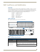
NXC-I/O10 Input/Output Control Card ............................................................11
Specifications.......................................................................................................... 11
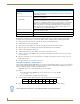
Pinouts, Signals, and I/O Mode Functions .............................................................. 12
NXC-I/O10 Channel Assignments ........................................................................... 12
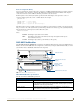
Setting the Switch/Voltage Mode Jumpers ............................................................ 12
Setting the Voltage Clamp Jumper (+12V or Open)............................................... 13
NXC-IRS4 4-Port IR/S Control Card ..................................................................15
Specifications.......................................................................................................... 15
Pinouts, Signals, and Functions .............................................................................. 16
NXC-IRS4 Channel Assignments ............................................................................. 16
Programming Information....................................................................................... 16
CAROFF ................................................................................................................................. 16
CARON................................................................................................................................... 16
CH .......................................................................................................................................... 17
CP........................................................................................................................................... 17
CTOF...................................................................................................................................... 17
CTON ..................................................................................................................................... 17
GET MODE............................................................................................................................. 18
IROFF ..................................................................................................................................... 18
POD ....................................................................................................................................... 18
POF ........................................................................................................................................ 18
PON ....................................................................................................................................... 18
PTOF ...................................................................................................................................... 19
PTON ..................................................................................................................................... 19
SET INPUT LINK ..................................................................................................................... 19
SET IO LINK............................................................................................................................ 19
SET MODE ............................................................................................................................. 20
SP........................................................................................................................................... 20
XCH........................................................................................................................................ 20
XCHM..................................................................................................................................... 20
NXC-REL10 Relay Control Card ........................................................................23
Specifications.......................................................................................................... 23
Pinouts and Functions............................................................................................. 23
NXC-REL10 Channel Assignments .......................................................................... 23
NXC-REL10 Connections/Wiring ............................................................................. 24
NXC-VAI4 Analog Voltage Control Card ..........................................................25
Specifications.......................................................................................................... 25
Pinouts and Functions............................................................................................. 26
Channel Assignments.............................................................................................. 26
NXC-VAI4 Output Level Assignments..................................................................... 28
NXC-VAI4 Input Level Assignments ........................................................................ 29
Programming Information....................................................................................... 29
AD MODE .............................................................................................................................. 29
DEFAULT................................................................................................................................ 29