
User Guide


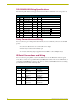

Connections and Wiring
6
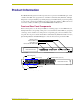
NXI NetLinx Integrated Controller
RS-232/422/485 Wiring Specifications
The following table lists the wiring specifications for the RS-232/422/485 connectors (ports 1-6).
Relay Connections and Wiring
You can connect up to 12 independent external relay devices to the Relay connectors on the NXI
(port 7).
! Connectors labeled A are for common; B are for output.
! Each relay is isolated and normally open.
! A metal commoning strip is supplied with each NXI to connect multiple relays.
IR/Serial Connections and Wiring
You can connect up to eight IR- or serial-controllable devices to the IR/Serial connectors (ports
8-15). These connectors accept an IR emitter (CC-NIRC) that mounts on the device's IR window, or
a mini-plug (CC-NSER) that connects to the device's control jack. The IR/Serial connector wiring
specifications are listed in the following table.
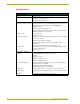
RS-232/422/485 Wiring Specifications
Pin Signal Function RS-232 RS-422 RS-485
1 GND Signal ground X X
2 RXD Receive data X
3 TXD Transmit data X
4 CTS Clear to send X
5 RTS Request to send X
6 TX + Transmit data X X (strap to pin 8)
7 TX - Transmit data X X (strap to pin 9)
8 RX + Receive data X X (strap to pin 6)
9 RX - Receive data X X (strap to pin 7)
10 12 VDC Power optional optional
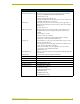
IR/Serial Connector Wiring Specifications
No. Port Signal Function
1 8 GND (-)
Signal 1 (+)
Signal GND
IR/Serial data
2 9 GND (-)
Signal 2 (+)
Signal GND
IR/Serial data
3 10 GND (-)
Signal 3 (+)
Signal GND
IR/Serial data
4 11 GND (-)
Signal 4 (+)
Signal GND
IR/Serial data