instruction manual NXD-CV7 and NXT-CV7 7" Modero Widescreen Video Touch Panels (Firmware version G4) Tou c h Pa n els an d A cc e ss o r ie s
AMX Limited Warranty and Disclaimer AMX Corporation warrants its products to be free of defects in material and workmanship under normal use for three (3) years from the date of purchase from AMX Corporation, with the following exceptions: • Electroluminescent and LCD Control Panels are warranted for three (3) years, except for the display and touch overlay components that are warranted for a period of one (1) year.
FCC Information This device complies with Part 15 of the FCC Rules. Operation is subject to the following two conditions: (1) this device may not cause harmful interference, and (2) this device must accept any interference received; including interference that may cause undesired operation. Federal Communications Commission (FCC) Statement This equipment has been tested and found to comply with the limits for a Class B digital device, pursuant to Part 15 of the FCC rules.
Table of Contents Table of Contents Introduction ...............................................................................................................1 CV7 Specifications ............................................................................................................ 3 CV7 Panels - Connector Layout........................................................................................ 6 CV7 Touch Panel Accessories ......................................................................
Table of Contents Installation .............................................................................................................. 29 Unpacking the Panel ....................................................................................................... 29 Installing the Internal Components.................................................................................. 29 Installing the No-Button Trim Ring ..................................................................................
Table of Contents Configuring a Wired Ethernet Connection....................................................................... 64 Step1: Configure the Panel’s Wired IP Settings.............................................................. 64 IP Settings section - Configuring a DHCP Address over Ethernet......................................... 64 IP Settings section - Configuring a Static IP Address over Ethernet...................................... 65 Step 2: Choose a Master Connection Mode Setting ..
Table of Contents Calibration Page................................................................................................................... 105 Secondary Connection Page ............................................................................................... 105 System Connection Page..................................................................................................... 109 Programming ..........................................................................................
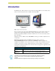
Introduction Introduction The NXT/D-CV7 7" Modero Widescreen Color Video Touch Panels (FIG. 1) are the industry’s first widescreen mini-touch panels and are available only through AMX. NXD-CV7 (front view) (FG2258-02) NXT-CV7 (front view) (FG2258-01) FIG. 1 Sample 7" Video Touch Panels These Color Video (CV) panels display NTSC/PAL/SECAM video formats within variable sized windows.
Introduction Key features common to both panels include: CV7 panels are based on the latest display technology and support AMX's 4th generation (G4) graphics which provide higher brightness, richer colors, and deeper contrast. The new G4 graphics technology is supported by the latest AMX TPDesign4 Touch Panel Design program (version 2.5 or higher). CV7 panels display eye-catching images and full-motion video on a large 16:9 image format, while providing a wide 100-degree top-to-bottom viewing angle.
Introduction CV7 Specifications The following table outlines the specifications for the 7" Widescreen Modero panels. Specifications for 7" Widescreen Video Touch Panels Dimensions (HWD): • NXA-RK7: metal rack-mount with black matte finish: (4 RU - rack units high) 6.97" x 19.0" x 0.50" (17.70 cm x 48.26 cm x 1.27 cm) • NXT-CV7 (Fully raised): 6.86" x 7.96" x 6.93" (17.40 cm x 20.20 cm x 17.60 cm) • NXT-CV7 (Fully lowered): 3.70" x 7.96" x 6.93" (9.40 cm x 20.20 cm x 17.
Introduction Specifications for 7" Widescreen Video Touch Panels (Cont.) Front Panel Components: Light sensor: • Photosensitive light detector for automatic adjustment of the panel brightness (a dim room results in a dimmer LCD display, and a bright room results in a brighter LCD display). Note: The light sensor can be adjusted via the Sensor Setup page (page 101). Motion sensor (PIR): • Proximity Infrared Detector to wake the panel when the panel is approached.
Introduction Specifications for 7" Widescreen Video Touch Panels (Cont.) Rear Panel Components (Cont.): Audio/Video connector: (Side panel location on NXD-Wall Mount panels) • RJ-45 connector for communication of differential audio/video signals to/from the touch panel (panel type dependant). This connector receives Composite video, Stereo (left/right) audio, and microphone audio. • Video is received via the NXA-AVB/ETHERNET Breakout Box. Configuring video windows for playback is done using TPDesign4.
Introduction Specifications for 7" Widescreen Video Touch Panels (Cont.) Optional Accessories:: • NXT-BP (FG2255-10) - Battery pack for Table Top panels. • NXT-CHG Kit (FG2250-50K) - 1 battery charger and 2 NXT-BP batteries • PSN2.8: Power Supply (FG423-17) with 3.5 mm mini-Phoenix connector • PSN4.4: Power Supply (FG423-45) with 3.5 mm mini-Phoenix connector • PSN6.5: Power Supply (FG423-41) with 3.
CV7 Touch Panel Accessories CV7 Touch Panel Accessories The following section outlines and describes the CV7 accessories (both the included and optional). NXA-AVB/ETHERNET Breakout Box (FG2254-10) The NXA-AVB/ETHERNET Breakout Box (FIG. 4) is included as part of the CV7 Kit configuration (panel and box) but can be purchased as a separate accessory. This box facilitates the installation and distribution of video, data, and audio to Modero touch panels located up to 200 feet (60.96 m) from the AVB box.
CV7 Touch Panel Accessories NXA-AVB/ETHERNET Specifications (Cont.) Rear Components: • 6-pin 3.5 mm Phoenix connector for in-bound (left/right channel) audio • 4-pin 3.5 mm Phoenix connector for out-bound (from microphone) audio • BNC connector (female) for Composite or Chroma (for video-capable panels only) • BNC connector (female) for luminance (for video-capable panels only) • RJ-45 connector for Ethernet input from the control system • 2-pin 3.
CV7 Touch Panel Accessories Direct connect Ethernet (CAT5) PSN power supply Audio (CAT5) between the NXA-AVB/ETHERNET Breakout Box NXD/T Non-video capable Touch Panels FIG. 6 Sample wiring configuration using CA Modero panels The breakout box unit can be mounted on either a horizontal flat surface or into an equipment rack (by removing the front screws and attaching it to an optional AC-RK).
CV7 Touch Panel Accessories • MIC OUT: 4-pin mini-Phoenix connector, divided into GND, OUT-, and OUT+ terminal connectors. An example of this cable is to strip the terminal ends of a 3.5mm mini-jack and insert them into their respective locations on the Mic Out port. This signal can be fed as a Line Level In to either an amplifier or an AMX VOL card. Either a balanced (+, -, and GND) or unbalanced (+ and GND) audio signal can be connected to this output.
CV7 Touch Panel Accessories Wiring the NXA-AVB/ETHERNET for Balanced Audio Professional audio equipment will often use balanced audio inputs and outputs, usually on 3-pin "XLR" connectors. A balanced audio signal consists of a pair of wires carrying the audio signal in anti-phase with each other (if one wire carries a positive voltage, the other carries an equal and opposite negative voltage).
CV7 Touch Panel Accessories Product Specifications Modero Table Top Cable Specifications Dimensions (HWD): • Length: 10 feet (3.048 m) Connectors: • Ethernet RJ-45 connector (White) routes Ethernet signals between the touch panel and the NXA-AVB/ETHERNET Breakout Box. • Audio/Video RJ-45 connector (Black) routes differential audio/video signals between the touch panel and the box. • 2-pin 3.5 mm mini-Phoenix power connector to route power from the external breakout box to the target panel.
CV7 Touch Panel Accessories The following table provides the wiring information (color coding) for each of the three available cable connectors on each side of the Modero Table Top Cable.
CV7 Touch Panel Accessories Each bundle of 4 twisted pairs includes a colored tape indicator for identification. NXA-WC80211B/CF 802.11b Wireless Card (FG2255-03) CV7 touch panels can connect to a wireless network using an optional internal AMX 802.11b compatible Wi-Fi Wireless Interface Card shown in FIG. 14. FIG. 14 NXA-WC80211B/CF Wireless Interface Card (WIC) This unit is certified and available for use in the United States (FCC), Canada (IC), Europe (CE) and Japan (TELEC).
CV7 Touch Panel Accessories Specifications for NXA-WC80211B/CF Modulation: • DSSS, DBSK, DQSK, CCK LED Indicators: • Power / Link activity Antenna: • 2, Ceramic (Diversity Supported) Receive Sensitivity: • @PER < 8% 11 Mbps: -83 dBm (max) 5.5 Mbps: -86 dBm (max) 2 Mbps: -89 dBm (max) 1 Mbps: -92 dBm (max) Operating Channels: • 11 Channels (USA, Canada) • 13 Channels (Europe) • 14 Channels (Japan) • 4 Channels (France) Wireless Restrictions: • In R&TTE countries, such as France, the 802.
CV7 Touch Panel Accessories Unscrew these four Housing Screws to remove the Circuit Board Cover Base Hinge Brackets (2) Touch Panel DO NOT REMOVE these screws They secure the plastic base front cover. FIG. 15 Location of the attachment screws underneath an NXT-CV7 panel base Note the location of the four plastic adhesive "feet".
CV7 Touch Panel Accessories 8. In a single motion, carefully pull both the Tilt Bracket cover plate and outer housing up and then out (away from the LCD panel) to expose the internal circuit board (FIG. 17). Outer Housing Tilt Bracket cover plate (must be removed first) Outer housing installation holes (located on front panel) Base FIG. 17 Removal of the outer housing and wireless card location Step 2: Upgrading internal components (Compact Flash and Wireless cards) 1.
CV7 Touch Panel Accessories 6. Insert the upgrade card into the connector opening with the arrow facing towards the pins, then push it in firmly until the contact pins are completely inside the flash card and securely attached to the connector. Card removal grooves On-board connector with contact pins Insert with arrow facing towards the pins Connector opening FIG. 19 Removing/installing a compact flash card 7. Repeat steps 3-6 for installation of the (optional) NXA-WC80211B/CF 802.
CV7 Touch Panel Accessories 9. Grasp both the LCD and housing and then rotate the entire unit back onto a flat surface. 10. Insert all connectors and apply power. Installation of the Wireless Card (WallMount Panel) These procedures involve removing the outer housing, installing the wireless card, and then securely replacing the outer housing back onto the NXD panel. The CV7 panels do not come factory installed with the NXA-WC802.11B/CF wireless interface card. This card must be ordered separately from AMX.
CV7 Touch Panel Accessories Caution: Speaker wires come connected to this side of the main board. Use caution when removing the back box. Connector Overlay must first be removed from the side of the NXD Compact Card Slot #1 located on the bottom slot FIG. 21 Removing the rear back box from the main unit The internal circuit board comes pre-wired to internal speakers located on the internal side of the back box.
CV7 Touch Panel Accessories NXA-CFSP Compact Flash (2116-3x) Every CV7 Modero panel is shipped with a 64 MB Compact Flash card (NXA-CFSP). If possible, upgrade the panel’s internal components (Compact Flash or wireless interface cards) prior to installing or using the panel.
CV7 Touch Panel Accessories Specifications for the NXT-BP Dimensions (HWD): • 0.69" x 3.50" x 5.81" (1.75 cm x 8.89 cm x 14.76 cm) Power (Voltage): • 11.1 Volts (nominal) Weight: • Single NXT-BP Power Pack: 1.0 lbs (0.
CV7 Touch Panel Accessories Before beginning the installation of the battery base to the Modero panel, verify the Modero panel has the latest firmware. Only the latest build incorporates the necessary updates for using the Modero with the NXA-BASE/1. From the Battery Base page, verify that the battery base is loaded with the latest NXA-BASE/1 firmware (v2.xx or higher). Checking the NXT-BP charge 1. Press the Battery Life Indicator button (FIG.
CV7 Touch Panel Accessories 3. Carefully insert the NXT-BP into the base until the battery securely fits onto the Battery Connector Port. Installing the NXA-BASE/1 below an NXT-CV7 Panel 1. Power Off the panel before attempting to attach the NXA-BASE/1. 2. Place the battery base (with battery) onto a flat/level surface. 3. Turn the battery locking slider (FIG.
CV7 Touch Panel Accessories 7. Align the rear pegs and gently push the rear of the panel downwards until it is mounted atop the battery base. The battery base CANNOT be hot-swapped. An NXT can not be receiving power (through a connected power supply) and then be connected to a battery base. Always POWER OFF the panel before installing the NXA-BASE/1. 8. Slide the rear battery locking slider in the opposite direction. This turns the latching mechanism and secures the panel to the base. 9.
CV7 Touch Panel Accessories Specifications for NXT-BP and NXT-CHG Dimensions (HWD): • 1.13" x 8.63" x 11.81" (2.86 cm x 21.91 cm x 30.00 cm) Power Requirements: • NXT-BP Battery Voltage - 11.1 Volts • NXT-CHG: 90 - 264 VAC, 47-63 Hz, Single Phase (using the included 24 VDC power supply) Weight: • 0.57 lbs (0.26 kg) Features: • Charge time for two depleted batteries: ~ 5 hours • Charge Rate: 2.
CV7 Touch Panel Accessories There is one LED indicator on the front of each battery slot that indicates the status of that slot. The blink patterns for these LEDs are described in the following table: • Off: No battery detected. • Green Flashing: Fast charging. • Green Solid: Fully charged. • Yellow Flashing: Recalibration in process. • Yellow/Green: Recalibration complete. • Yellow Solid: Standby (waiting for other battery to charge).
CV7 Touch Panel Accessories 28 7" Modero Widescreen Touch Panels
Installation Installation NXT panels are mounted onto flat (horizontal) surfaces in either a stand-alone or combo (NXT atop an NXA-BASE/1 battery base) configuration. NXD panels are installed into either a pre-wall surface (using a CB-TP7 conduit/wallbox) or a solid surface (using either solid surface or drywall screws). It is recommended that if you are planning on upgrading your panel components (flash and wireless), you do so before beginning any panel installations. Unpacking the Panel 1.
Installation Removing the Internal Faceplate from the panel exposes the pushbuttons and light pipes along the inside of the Internal Faceplate. 4. Gently tug along the edges of the Button Trim Ring and work your way around the edges to remove it from the Faceplate (FIG. 30).
Installation No-Button Trim Ring Hollow button openings Faceplate (outer surface shown) FIG. 31 Inserting the No-Button Trim Ring Installing the Button Trim Ring The outer No-Button Trim Ring is secured to the Faceplate with plastic latches. In order to re-install the Button Trim Ring back onto an NXD panel which has had the default Button Trim Ring features removed; you must first remove the No-Button Trim Ring: 1.
Installation CV7 Panel/enclosure Button latch Trim Ring Latches Light Pipe latch (black) Button and Light Pipe removal (showing the internal surface of Faceplate) No-Button Trim Ring Faceplate (outside surface shown) FIG. 32 Removing the No-Button Trim Ring 8. Gently insert the Button Trim Ring latches into their corresponding openings on the outer surface of the internal Faceplate (FIG. 33). Button Trim Ring Faceplate (outer surface shown) Button openings FIG. 33 Inserting the Button Trim RIng 9.
Installation Pre-Wall Installation of the Conduit Box Wall Mount panels (NXDs) are contained within an outer housing (back box). This back box is not removed when installing the NXD into a Conduit Box (CB-TP7). The back box is only removed to gain access for the replacement of the internal components. INSTALLER: LEAVE A GAP BETWEEN THE STUD AND CONDUIT BOX MOUNTING TABS TO ACCOMMODATE THE DRYWALL or SHEETROCK.
Installation 3. Remove the wiring knockouts from the left side of the conduit box (CB-TP7) (FIG. 34) to accommodate the cables being threaded through to the NXD touch panel. Remember that when mounting this conduit box, the NXD mounting tabs must lie flush against the outside of the sheetrock. 4. Thread the incoming power, RJ-45 audio/video, Ethernet, and USB wiring through the knockouts (use of the left wiring knockouts are recommended with this installation).
Installation 2. Verify the incoming power, RJ-45 audio/video, Ethernet, and USB cables have been properly threaded through the wiring knockouts on the left of the conduit box. Leave enough slack in the wiring to accommodate any re-positioning of the panel. 3. Connect all data and power wiring connectors to their corresponding locations along the side of the (un-powered) NXD touch panel.
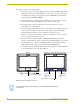
Installation 1. Remove any screws or nails from the drywall before beginning. 2. Cut out the surface for the NXD Wall Mount unit using the dimensions shown in FIG. 36. Be sure to cut out the three notches along the sides to accommodate the three corresponding drywall expansion clips (included). FIG. 36 NXD-CV7 Wall Mount panel dimensions using expansion clips 3. Remove the Faceplate/bezel (A in FIG. 37) from the main NXD unit (B in FIG. 37) by gripping the faceplate and pulling with gentle outward force.
Installation 3 notches are required to accommodate the three expansion clips (included) Install the 3 included drywall clip sets into these locations Drywall Clip (3) Mounting Tab A - Faceplate /Trim Ring B - Main NXD unit consists of the touch panel and back box FIG. 37 Wall Mount panel (NXD) installation configuration for drywall surfaces Don’t disconnect the connectors from the touch panel. The unit must be installed with the attached connectors before being inserted into the drywall. 6.
Installation 12. Reconnect the terminal RJ-45, Ethernet, USB, and any optional audio/video wiring to their respective locations on either the NXA-AVB/ETHERNET Breakout Box, Ethernet port, or NetLinx Master. 13. Reconnect the terminal power connector on the PSN and apply power to the panel. Installing the NXD into a Flat Surface using #4 screws Mounting screws (#4-40, included) are secured through two sets of circular holes located at the left and right sides of the NXD-CV7.
Installation 4. Thread the incoming power, RJ-45, Ethernet, USB, and any optional audio/video wiring (from their terminal sources) through the surface opening. Leave enough slack in the wiring to accommodate any re-positioning of the panel. 5. Connect all data and power wiring connectors to their corresponding locations along the left side of the (un-powered) NXD touch panel. Verify that the terminal end of the power cable is not connected to a power source before plugging in the 2-pin power connector.
Installation 9. Insert and secure four #4-40 Mounting Screws (included) into their corresponding holes located along the sides of the NXD-CV7 (using a grounded Phillips-head screwdriver) until the unit is secure and flush against the wall (FIG. 39). 10. Replace the Faceplate/Trim Ring on the main unit. Make sure to align the Microphone, Light, and PIR Motion sensor locations to their respective openings on the front bezel/faceplate. 11.
Installation 11. Reconnect the terminal RJ-45 audio/video, Ethernet, and USB wiring to their respective terminal locations on either the NXA-AVB/ETHERNET Breakout Box, Ethernet port, or NetLinx Master. 12. Reconnect the terminal power connector on the PSN and apply power. Wiring Guidelines for the CV7 Panels CV7 panels require 12 VDC power from a PSN NetLinx Power Supply to operate properly. The panels connect to the power supply via a 2-pin 3.5 mm mini-Phoenix connector.
Installation Audio/Video RJ-45 Connections and Wiring The following table shows the signal and pinout/pairing information used on the RJ-45 Audio and Video connections.
Installation FIG. 42 RJ-45 wiring diagram Connecting and Using USB Input Devices The CV7 panel can have up to two USB-capable input devices connected for use on its different firmware and TPD4 panel pages. These input devices can consist of a keyboard or mouse. USB-connected input devices are not detected and recognized by the panel until power is cycled to the unit. A mini-USB connection is only detected after it is installed onto an active panel.
Installation 44 7" Modero Widescreen Touch Panels
Panel Calibration Panel Calibration This section outlines the steps for calibrating the touch panel. It is recommended that you calibrate the panel before its initial use and after completing a firmware download. Modero panels are factory setup with specific demo touch panel pages. The first splash screen that appears indicates the panel is receiving power, beginning to load firmware, and preparing to display the default touch panel pages.
Panel Calibration The request to touch the crosshairs is the first on-screen message Calibration successful is the second on-screen message that appears after the calibration process is completed On-screen crosshairs used for calibration of the touch device FIG. 45 Touch Panel Calibration Screens 3. After the "Calibration Successful.." message appears, press anywhere on the screen to continue and return to the Setup page.
Configuring Communication Configuring Communication Communication between the Modero panel and the Master is done using either USB or ETHERNET (DHCP or Static IP). Ethernet communication can be achieved through either a direct connection (Ethernet) or through the use of the optional NXA-WC802.11B/CF wireless interface card. Before commencing, verify you are using the latest NetLinx Master firmware. Verify the NetLinx Studio program being used is Version 2.3 or higher.
Configuring Communication 7. Press the on-screen Reboot button to restart the panel and incorporate any changes. FIG. 48 Protected Setup page Before continuing, open NetLinx Studio 2.3. This program assists in developing a System Number, Master IP/URL, and Master Port number. Refer to your NetLinx Master’s instruction manuals for more information. 8. Obtain the System Number and Master IP Address from NetLinx Studio. This information must be specific for the system used with the configured Modero panel.
Configuring Communication It is recommended that firmware KIT files only be transferred over a direct connection and only when the panel is connected to a power supply. If battery power or wireless connection fails during a firmware upgrade, the panel flash file system may become corrupted. The mini-USB connector MUST be plugged into an already active panel before the PC can recognize the connection and assign an appropriate USB driver.
Configuring Communication No connection is established until the Virtual Master becomes active within Studio Red Connection Status icon indicates no connection to a Virtual Master Green Connection Status icon indicates communication to a Virtual Master FIG. 50 USB System Connection page - using a USB Connection Type 5. Toggle the blue Type field (from the Master Connection section) until the choice cycles to USB.
Configuring Communication This window notifies you that the panel has been detected by the PC as a USB-compliant device and the PC is installing an appropriate USB driver to establish a proper communication to the panel. This driver was installed on your PC during the installation of the latest NetLinx Studio and TPDesign4 software application installations. These applications should be installed prior to setting up a USB connection to the panel.
Configuring Communication USB connected touch panel (showing the recognized panel) FIG. 52 Device Manager dialog showing USB device A Virtual NetLinx Master (VNM) is used when the target panel is not connected to a physical NetLinx Master. In this situation, the PC takes on the functions of a Master via a Virtual NetLinx Master.
Configuring Communication The next time this device is connected to the computer it will appear as a new hardware device and will need to be associated again with the driver (refer to Step 2: Confirm the Installation of the USB Driver on the PC section on page 49. Step 4: Use the USB to Configure a Virtual Master (using NetLinx Studio) When configuring your panel to communicate via USB with a Virtual Master (on your PC), ONLY the USB connection option must be selected within the Type field.
Configuring Communication 9. Click OK three times to close the open dialogs, save your settings, and return to the main NetLinx Studio application. 10. Click the OnLine Tree tab in the Workspace window to view the devices on the Virtual System. The default System value is one. 11. Right-click on the Empty Device Tree/System entry and select Refresh System to re-populate the list.
Configuring Communication FIG. 55 Using USB for Virtual Master communication Secondary Connection Page - Wireless Access Overview IP Routing The behavior of the wireless routing is largely dependent on the wired network interface. Although the panel can be connected to two networks simultaneously it may only have one gateway. If the wired network was successfully set up and a gateway was obtained; then the default route for all network traffic will be via the wired network.
Configuring Communication communication parameters must match those of the pre-installed wireless interface card installed within the panel. The CV7 touch panels allow users to connect to a wireless network through their use of the optional AMX 802.11b wireless interface card. This internal card transmits data using the 802.11b signals at 2.4 GHz. Before beginning, there are several concepts that should be explained: Wireless Access Points are the cornerstone of any wireless network.
Configuring Communication Configuring a Wireless Network Access When working with a wireless card, the first step is to configure wireless communication parameters within the Secondary Connection page. This page only configures the card to communicate to a target WAP (such as the NXA-WAP200G), it is still necessary to tell the panel which Master it should be communicating with.
Configuring Communication This information can be found in either the Workspace - System name > Define Device section of your code (that defines the properties for your panel), or in the Device Addressing/Network Addresses section of the Tools > NetLinx Diagnostics dialog. 8. Setup the security and communication parameters between the wireless card and the target WAP by configuring the Wireless Settings section on this page.
Configuring Communication Step 2: Configure the Card’s Wireless Security Settings The second step to successfully setting up your wireless card is to configure the Wireless Settings section of the Secondary Connection page. The section configures both the communication and security parameters from the internal wireless card to the WAP. The procedures outlined within the following sections use an NXA-WAP200G and the target WAP.
Configuring Communication One of the most common problems associated with connection to a WAP arise because the SSID was not entered properly. You must maintain the same case when entering the SSID information. ABC is not the same as Abc. 8. Toggle the Authentication field to an Open System (default). Open System Authentication allows any device to join the network if the panel’s SSID matches the WAP’s SSID. 9. Toggle the Encryption field until it reads Clear Text (default).
Configuring Communication 2. Power-up the panel (this allows it to detect the card). 3. Press the Protected Setup button (located on the lower-left of the panel page) to open the Protected Setup page and display an on-screen keypad. 4. Enter 1988 into the Keypad’s password field and press Done when finished. 5. Press the Secondary Connection button (located on the lower-left) to open the Secondary Connection page. 6. Locate the Wireless Settings section of the Secondary Connection page (FIG. 58).
Configuring Communication Shared Key Authentication requires that the panel and the Wireless Access Point have the same WEP Key to authenticate. 9. Toggle the Encryption field (FIG. 58) until it reads WEP64 or WEP128. The 64/128 selection reflects the bit-level of encryption security. This WEP encryption level must match the encryption level being used on the WAP WEP will not work unless the same Default Key is set on both the panel and the Wireless Access Point.
Configuring Communication This series of hex digits (26 hex digits for a 128-bit encryption key) should be entered as the Current Key into both the WAP and onto other communicating Modero panels by using the WEP Key dialog (FIG. 60). FIG. 60 WEP Key # Keyboard 13. Write down this Current Key string value for later entry into your WAP’s WEP Key field (typically entered without colons) and into the communicating panel’s Current Key field (FIG. 58). 14.
Configuring Communication Configuring multiple wireless Moderos to communicate to a target WAP200G 1. For each communicating touch panel, complete all of the steps outlined within the previous Configuring the Modero’s wireless card for secured access to a WAP200G section on page 60. 2. Navigate back to the Wireless/Secondary Connection page on each panel. 3. Verify that all communicating Modero panels are using the same SSID, encryption level, Default Key #, and an identical Current Key value.
Configuring Communication DHCP will register the unique MAC Address (factory assigned) on the panel and once the communication setup process is complete, reserve an IP Address, Subnet Mask, and Gateway values from the DHCP Server. 4. Press the optional Host Name field to open a Keyboard and enter the Host Name information. 5. Press Done after you are finished assigning the alpha-numeric string of the host name. 6. Do not alter any of the remaining greyed-out fields in the IP Settings section.
Configuring Communication Step 2: Choose a Master Connection Mode Setting There are three Ethernet MODE settings used in the Master Connection section of the System Connection page. URL is the most common method. Master Connection MODE options: • URL (Uniform Resource Locator) is the address that defines the route to a file on the Web or any other Internet facility. In this system, the panel acts as a "Client" and the Master acts as a Server (in that Clients attach to it).
Configuring Communication Obtained from NetLinx Master FIG. 61 System Connection page Master Connection section - Virtual Master communication over Ethernet When configuring your panel to communicate with a Virtual Master (on your PC) via Ethernet, the Master IP/URL field must be configured to match the IP Address of the PC and make sure to use the Virtual System value assigned to the Virtual Master within NetLinx Studio. Before beginning: 1.
Configuring Communication 5. Click on the NetLinx Master radio button (from the Platform Selection section) to indicate that you are working as a NetLinx Master. 6. Click on the Virtual Master radio box (from the Transport Connection Option section) to indicate you are wanting to configure the PC to communicate with a panel. Everything else such as the Authentication is greyed-out because you are not going through the Master’s UI. 7.
Configuring Communication By selecting URL, the System Number field becomes read-only (grey) because the panel pulls this value directly from the communicating target Master (virtual or not). A Virtual Master system value can be set within the active AMX software applications such as: NetLinx Studio, TPD4, or IREdit. 16. Press the Master IP/URL field to open a Keyboard and enter the IP Address of the PC used as the Virtual Master. 17.
Configuring Communication Master Connection section - NetLinx Master Ethernet IP Address - Listen Mode In this mode, you must add the Modero panel IP Address into the URL List of the Master (using NetLinx Studio). This mode sets the Modero panel to "listen" for broadcasts from the Master (using the panel IP from its URL list). 1. Obtain either a Static IP for the Modero panel (from your System Administrator) or a DHCP Address from the IP Settings of the System Connection page.
Configuring Communication 11. Press the on-screen Reboot button to save any changes and restart the panel. Master Connection section - NetLinx Master Ethernet IP Address - Auto Mode In this mode, enter the System Number of the NetLinx Master. This mode instructs the Modero to search for a Master that uses the same System Number (assigned within the Master Connection section) and resides on the same Subnet as itself. 1.
Configuring Communication FIG. 65 G4 Web Control page 6. Press the Enable/Enabled button until it toggles to Enabled (light blue color). 7. The Network Interface Select field is read-only and displays the method of communication to the web. Verify you have selected the proper interface connection as this field does not auto-detect the connection type being used (see below). Wired is used when a direct Ethernet connection is being used for communication to the web.
Configuring Communication 12. From the Web Password keyboard, enter a unique alpha-numeric string to be assigned as the G4 Authentication session password associated with VNC web access of this panel. 13. Press Done after you are finished assigning the alpha-numeric string for the Web Control password. 14. Press the Web Control Port field to open the Web Port Number keypad. 15. Within the keypad, enter a unique numeric value to be assigned to the port the VNC Web Server is running on.
Configuring Communication Compatible devices field (showing G4 WebControl links) G4 panels Compression Options FIG. 67 WebControls window (populated with panels) Using your NetLinx Master to Control the G4 panel Once the Master’s IP Address has been set through NetLinx Studio (version 2.3 or higher): 1. Follow the procedures mentioned above to communicate to the target NetLinx Master through an IP Address. 2. Enter a valid user name and password into the fields within the Login dialog. 3.
Configuring Communication 6. Click Yes from the Security Warning popup window to agree to the installation of the G4 Web Control application on your computer. This application contains the necessary Active X and VNC client applications necessary to properly view and control the panel pages from your computer. The G4 Web Control application is sent by the panel to the computer that is used for communication. Once the application is installed, this popup will no longer appear.
Configuring Communication 76 7" Modero Widescreen Touch Panels
Upgrading Modero Firmware Upgrading Modero Firmware Before beginning the Upgrade process: Setup and configure your NetLinx Master. Refer to the your particular NetLinx Master Instruction Manual for detailed setup procedures. Calibrate and prepare the communication pages on the Modero panel for use. Refer to the Panel Calibration section on page 45. Refer to the NetLinx Studio version 2.3 or higher Help file for more information on uploading files via Ethernet.
Upgrading Modero Firmware 4. Toggle the blue Type field (from the Master Connection section) until the choice cycles to USB. ALL fields are then greyed-out and read-only, but still display any previous network information. 5. Press the Back button on the touch panel to return to the Protected Setup page. 6. Press the on-screen Reboot button to both save any changes and restart the panel.
Upgrading Modero Firmware 5. Click on the Virtual Master radio box (from the Transport Connection Option section) to indicate you are wanting to configure the PC to communicate directly with a panel. Everything else such as the Authentication is greyed-out because you are not going through the Master’s UI. 6. Click the Edit Settings button (on the Communications Settings dialog) to open the Virtual NetLinx Master Settings dialog (FIG. 70). 7. From within this dialog enter the System number (default is 1).
Upgrading Modero Firmware Showing the Virtual Master firmware version and device number Shows NetLinx Studio version number Showing the current Modero panel firmware version and device number FIG. 71 NetLinx Workspace window (showing the panel connection via a Virtual NetLinx Master) The panel firmware is shown on the right of the listed panel. Download the latest firmware file from www.amx.com and then save the KIT file to your computer. 5.
Upgrading Modero Firmware 11. Click the Reboot Device checkbox. This causes the touch panel to reboot after the firmware update process is complete. The reboot of the panel can take up 30 seconds after the firmware process has finished. 12. Click Send to begin the transfer. The file transfer progress is indicated on the bottom-right of the dialog (B in FIG. 72). 13. As the panel is rebooting, temporarily unplug the USB connector on the panel until the panel has completely restarted. 14.
Upgrading Modero Firmware List of previously saved IP Addresses FIG. 73 Assigning Communication Settings and TCP/IP Settings 9. From within the TCP/IP dialog click New to enter the IP information for a new IP Address or select from the list of previously entered IP Address and alter their properties by clicking the Edit button and making your changes. 10. Enter the IP Address into the TCP/IP Address field. This information is obtained from either your System Administrator or obtained from the Master. 11.
Upgrading Modero Firmware 4. Click Done to accept the new value and return to the System Configuration page. 5. Do not alter the Master Port Number value (this is the default value used by NetLinx). 6. Press the Back button to return to the Protected Setup page and press the on-screen Reboot button to restart the panel and save any changes. Step 3: Verify and Upgrade the panel firmware via an IP 1. Click the OnLine Tree tab in the Workspace window to view the devices on the System.
Upgrading Modero Firmware Selected Firmware file Description field for selected KIT file Firmware download status Device and System values listed in the Workspace window must match the System and Device values FIG. 75 Send to NetLinx Device dialog (showing Modero firmware update via IP) 10. Click the Reboot Device checkbox. This causes the touch panel to reboot after the firmware update process is complete. The reboot of the panel can take up 30 seconds after the firmware process has finished. 11.
Firmware Pages and Descriptions Firmware Pages and Descriptions This section describes each firmware page and their specific functional elements. Setup Navigation Buttons These Setup Navigation Buttons (FIG. 76) appear on the left of the panel screen when the Setup page is currently active. Modero Setup Navigation Buttons FIG.
Firmware Pages and Descriptions Setup Navigation Button Elements (Cont.) Protected Setup: Press the Protected Setup button to access the Protected Setup page section that provides access to the panel’s sensors, calibration features, and connection settings. • Refer to both the Protected Setup Navigation Buttons section on page 97 and Protected Setup Page section on page 98 for more detailed information.
Firmware Pages and Descriptions Setup Page Elements (Cont.) Connection Status: Displays whether the panel is communicating externally, the encryption status of the communicating Master, what connection type is being used (Ethernet or USB), and what System the panel is a part of. This visual display of the connection status is also reflected at the upper-right of each firmware page.
Firmware Pages and Descriptions Project Information Page The Project Information page displays the TPDesign4 (TPD4) project file properties currently loaded on the selected Modero panel (FIG. 78). Refer to the TPDesign4 Touch Panel Program instruction manual for more specific information on uploading TPDesign4 files to a panel. FIG.
Firmware Pages and Descriptions Project Information Page Elements (Cont.) AMX IR 455k Assigned Port: Displays the AMX 455 kHz IR channel port used by the IR receiver on the panel. This information is pulled by the panel from AMX IR Receivers section of the TPD4 Project Properties > IR Emitters & Receivers tab. • For IR reception, this is the port that reports a push on for the corresponding IR code. • IR receivers and transmitters on G4 panels share the device address number of the panel.
Firmware Pages and Descriptions Panel Information Page Elements (Cont.) Setup Port: Displays the setup port information/value being used by the panel. High Port: Displays the high port (port count) value for the panel. High Address: Displays the high address (address count) value for the panel. High Channel: Displays the high channel (channel count) value for the panel. High Level: Displays the high level (level count) value being used by the panel.
Firmware Pages and Descriptions The only way to modify a panel’s time, without altering the Master, is to use NetLinx Code. The elements of the Time & Date Setup page are described in the table below: Time & Date Setup Page Elements Back: Returns you to the previously active touch panel page without saving changes (to save changes, use the Set Time button).
Firmware Pages and Descriptions Volume Page The Volume page (FIG. 81) (accessed by pressing the Audio Adjustments button on the Setup page) allows you to adjust the master volume parameters and default panel sounds on the panel. FIG. 81 Volume configuration page The elements of the Volume page are described in the table below: Volume Page Elements Back: Saves the changes and returns you to the previously active touch panel page.
Firmware Pages and Descriptions Volume Page Elements (Cont.) Default Panel Sounds: Sets the Modero panel to play either the default Button Hit sound (when you touch an active button) and/or the default Button Miss sound (when you touch a non-active button or any area outside of the active button). Supported sampling rates for WAV The following is a listing of supported sampling rates associated for WAV files played on CV7 panels. Some WAV files currently played on Modero's may not work on these panels.
Firmware Pages and Descriptions The elements of the Video Setup page are described in the table below: Video Setup Page Elements Back: Saves the changes and returns you to the previously active touch panel page. Connection Status icon: This visual display of the connection status allows the user to have a current visual update of the panel’s connection status regardless of what page is currently active.
Firmware Pages and Descriptions Battery Base Page This page (FIG. 83) allows you to alter/set the power warning preferences, monitor battery status information, and alter the display times for the battery warnings. The fields on this page are populated with information after the panel is connected to an optional NXA-BASE/1 Battery Base containing a single NXT-BP battery. FIG. 83 Battery Base page This page is ONLY available on CV7 Table Top panels (NXT) using an NXA-BASE/1.
Firmware Pages and Descriptions Battery Base Page Elements (Cont.) Very Low Battery Warning: The Very Low Battery Warning UP/DN buttons alter the time value (in minutes) available on the battery (for use) before the panel displays a very low battery warning. This indicates a near-term panel shutdown. • Range = 3 - 15, default = 5 min. - This value can never exceed the Low Battery Warning value.
Firmware Pages and Descriptions Protected Setup Navigation Buttons The Protected Setup Navigation Buttons (FIG. 84) appear on the left of the panel screen when the Protected Setup page is currently active. Modero Protected Setup Navigation Buttons FIG.
Firmware Pages and Descriptions Protected Setup Page The Protected Setup page (FIG. 85) centers around the properties used by the panel to properly communicate with the NetLinx Master. Enter the factory default password (1988) into the password keypad to access this page. Provides access to the panel firmware pages by enabling the grey front setup access button: - Setup page (after a 3 second press/hold) - Calibration page (after a 6 second press/hold) FIG.
Firmware Pages and Descriptions Protected Setup Page Elements (Cont.) System Recovery: Allows you to either reset the touch panel to factory default settings and/or wipe out all existing touch panel pages: • The Reset System Settings button allows a user to wipe out all current configuration parameters on the touch panel (such as IP Addresses, Device Number assignments, Passwords, and other presets). - Pressing this button launches a Confirmation dialog (FIG. 86) which asks you to confirm your selection.
Firmware Pages and Descriptions G4 Web Control Page The G4 Web Control page (FIG. 88) centers around enabling and disabling both the display and control of your panel (via the web). An external PC running a VNC client (installed during the initial communication to the G4 panel) makes this possible. FIG. 88 G4 Web Control page Each panel supports the open standard Virtual Network Computing (VNC) interface.
Firmware Pages and Descriptions G4 Web Control Page Elements (Cont.) G4 Web Control Settings (Cont.): Web Control Port Allows you to enter the port value that the VNC Web Server runs on. • Default value is 5900. Maximum Number of Connections This read-only field displays the maximum number of users that can be simultaneously connected to the target panel via the web. • Default value is 1.
Firmware Pages and Descriptions A light level value between the Minimum and Maximum DIM Mode values delivers an average light level. The DIM mode Min Level can never exceed the DIM Mode Max Level. The elements of the Sensor Setup page are described in the table below: Sensor Setup Page Elements Back: Saves the changes and returns you to the previously active touch panel page.
Firmware Pages and Descriptions Sensor Setup Page Elements (Cont.) Motion Sensor: Provides the following fields: • The Motion Detection field displays a reactive button that changes color (illuminates) and displays the words "Motion Detected" when motion is detected by the Modero panel’s front motion sensor. • The Motion Sensor Port field indicates the port used to report the motion sensor channel back to the NetLinx Master (set in TPD4) (read-only).
Firmware Pages and Descriptions 7. Set the Minimum Dimmer Brightness (Dim Mode Min Level) to a comfortable level by sitting in front of the panel. You should be able to comfortably see someone sitting behind the panel without being “blinded” by the panel. 8. Move around the panel and block the direct or indirect light from the room fixtures with your body. Take note of the drop in the lighting level being detected by the panel in response to your movements. 9.
Firmware Pages and Descriptions Calibration Page This page (FIG. 92) allows you to calibrate the touch panel using the pre-selected touch driver. Press and hold the grey Front Setup Access button (below the Modero LCD) for 6 seconds to access the Calibration page. Press the crosshairs to calibrate the panel and return to the last active firmware page.
Firmware Pages and Descriptions IP Settings section Wireless Settings section Red fields are user-editable Blue fields cycle through choices Grey fields are read-only Changes on this page take effect after using the BACK button to return to the previous page FIG.
Firmware Pages and Descriptions Secondary Connection Page Elements (Cont.) Access Point MAC Address: This value is factory set by the manufacturer of the Wireless Access Point (WAP). When communicating with a WAP200G enter the MAC Address (BSSID) of the target WAP as the Access Point MAC Address. Refer to the WAP200G Instruction Manual for more detailed information on the interaction between these two product lines.
Firmware Pages and Descriptions Secondary Connection Page Elements (Cont.) Wireless Settings (Cont.): Generate (Passphrase) Pressing the Generate button displays an on-screen keyboard which allows you to enter a passphrase and then AUTOMATICALLY generate all four WEP keys which are compatible only among Modero panels. • Note: The code key generator on Modero panels use the same key generation formula.
Firmware Pages and Descriptions Secondary Connection Page Elements (Cont.) Wireless Settings (Cont.): Channel The RF channel being used for connection to the WAP (read -only). • This is determined through the WAP. Link Quality Displays the current quality of the link (as descriptive colored text) from the wireless NIC to the Wireless Access Point in real time. • The bargraph has been replaced with a descriptions: None, Poor, Fair, Good, Very Good, and Excellent.
Firmware Pages and Descriptions The elements of the System Connection page are described in the table below: System Connection Page Elements Back: Saves the changes and returns you to the previously active touch panel page. Connection Status icon: This visual display of the connection status allows the user to have a current visual update of the panel’s connection status regardless of what page is currently active.
Firmware Pages and Descriptions System Connection Page Elements (Cont.) Master Connection: Type Sets the NetLinx Master communication values: Sets the NetLinx Master to communicate with the panel via either USB or Ethernet. This is based on the cable connection from the rear. ICSNet is not a supported option on this panel. • Ethernet is a CAT-5 cable (10/100Base T terminated in an RJ-45 connector) used to network computers together and is used in most LAN (local area networks).
Firmware Pages and Descriptions 112 7" Modero Widescreen Touch Panels
Programming Programming You can program the touch panel, using the commands in this section, to perform a wide variety of operations using Send_Commands and variable text commands. A device must first be defined in the NetLinx programming language with values for the Device: Port: System (in all programming examples - Panel is used in place of these values and represents all Modero panels). Verify you are using the latest NetLinx Master firmware. Verify the NetLinx Studio program being used is version 2.
Programming Page Commands (Cont.) @DPG Syntax: Delete a specific popup page from specified popup group if it exists. Variable: "'@DPG-;'" popup page name = 1 - 50 ASCII characters. Name of the popup page. popup group name = 1 - 50 ASCII characters. Name of the popup group. Example: SEND_COMMAND Panel,"'@DPG-Popup1;Group1'" Deletes the popup page ’Popup1’ from the popup group ’Group1’.
Programming Page Commands (Cont.) @PPA Close all popups on a specified page. If the page name is empty, the current page is used. Same as the ’Clear Page’ command in TPDesign4. Syntax: "'@PPA-'" Variable: page name = 1 - 50 ASCII characters. Name of the page the popup is displayed On. Example: SEND_COMMAND Panel,"'@PPA-Page1'" Close all popups on Page1. @PPF Deactivate a specific popup page on either a specified page or the current page.
Programming Page Commands (Cont.) @PPM Set the modality of a specific popup page to Modal or NonModal. A Modal popup page, when active, only allows you to use the buttons and features on that popup page. All other buttons on the panel page are inactivated. Syntax: "'@PPM-;'" Variable: popup page name = 1 - 50 ASCII characters. Name of the popup page. mode = NONMODAL converts a previously Modal popup page to a NonModal. MODAL converts a previously NonModal popup page to Modal.
Programming Page Commands (Cont.) @PSE Set the show effect for the specified popup page to the named show effect. Syntax: "'@PSE-;'" Variable: popup page name = 1 - 50 ASCII characters. Name of the page the popup is displayed On. show effect name = Refers to the popup effect name being used. Example: SEND_COMMAND Panel,"'@PSE-Popup1;Slide from Left'" Sets the Popup1 show effect name to ’Slide from Left’. @PSP Set the show effect position.
Programming Page Commands (Cont.) PPOF Deactivate a specific popup page on either a specified page or the current page. If the page name is empty, the current page is used (see example 2). If the popup page is part of a group, the whole group is deactivated. This command works in the same way as the ’Hide Popup’ command in TPDesign4. Syntax: "'PPOF-;'" Variable: popup page name = 1 - 50 ASCII characters. Name of the popup page. page name = 1 - 50 ASCII characters.
Programming Programming Numbers The following information provides the programming numbers for colors, fonts, and borders. Colors can be used to set the colors on buttons, sliders, and pages. The lowest color number represents the lightest color-specific display; the highest number represents the darkest display. For example, 0 represents light red, and 5 is dark red. RGB triplets and names for basic 88 colors RGB Values for all 88 Basic Colors Index No.
Programming RGB Values for all 88 Basic Colors (Cont.) 120 Index No.
Programming RGB Values for all 88 Basic Colors (Cont.) Index No. Name Red Green Blue 80 Grey8 119 119 119 81 Grey10 85 85 85 82 Grey12 51 51 51 83 Grey13 34 34 34 84 Grey2 221 221 221 85 Grey11 68 68 68 86 Grey14 17 17 17 87 Black 0 0 0 255 TRANSPARENT 99 53 99 Font styles and ID numbers Font styles can be used to program the text fonts on buttons, sliders, and pages.
Programming Border styles and Programming numbers Border styles can be used to program borders on buttons, sliders, and popup pages. Border Styles and Programming Numbers No. Border styles No.
Programming TPD4 Border Styles by Name (Cont.) No. Border styles No.
Programming TPD4 Border Styles by Name (Cont.) No. Border styles No.
Programming "^" Button Commands ^ANI Syntax: Run a button animation (in 1/10 second). Variable: "'^ANI-,,,
Programming "^" Button Commands (Cont.) ^BCB Only if the specified border color is not the same as the current color. Set the border color to the specified color. Note: Color can be assigned by color name (without spaces), number or R,G,B value (RRGGBB or RRGGBBAA). Syntax: "'^BCB-,
Programming "^" Button Commands (Cont.) ^BCT Only if the specified text color is not the same as the current color. Set the text color to the specified color. Note: Color can be assigned by color name (without spaces), number or R,G,B value (RRGGBB or RRGGBBAA). Syntax: "'^BCT-,
Programming "^" Button Commands (Cont.) ^BIM Syntax: Set the input "'^BIM-,'" mask for the Variable: specified address. variable text address range = 1 - 4000. input mask = Refer to the Text Area Input Masking section on page 170 for character types. Example: SEND_COMMAND Panel,"'^BIM-500,AAAAAAAAAA'" Sets the input mask to ten ’A’ characters, that are required, to either a letter or digit (entry is required). ^BLN The maximum number of lines to remove is 240.
Programming "^" Button Commands (Cont.) ^BMC Button copy command. Copy attributes of the source button to all the destination buttons. Note that the source is a single button state. Each state must be copied as a separate command. The section represents what attributes will be copied. All codes are 2 char pairs that can be separated by comma, space, percent or just ran together.
Programming "^" Button Commands (Cont.) ^BMF Set any/all button parameters by sending embedded codes and data. Syntax: "'^BMF-,
Programming "^" Button Commands (Cont.) ^BMF (Cont.) For some of these commands and values, refer to the RGB Values for all 88 Basic Colors table on page 119. ’%CF’ = Set Fill Color. ’%CB’ = Set Border Color. ’%CT’ = Set Text Color. ’%SW<1 or 0>’ = Show/hide a button. ’%ST