Notice CORRECTION PRODUCTION CHANGE SERVICE FLASH ADDED INFORMATION FILE NO. Please add this notice to the TECHNICAL & SERVICE MANUAL listed below. Category : DC INVERTER SPLIT SYSTEM AIR CONDITIONER Model : KHS0971 + CH0971 KHS1271 + CH1271 Date : Aug., 2006 Destination : North America Serial No. : Issue Number : 1 Indoor Model No. Product Code No. Outdoor Model No. Product Code No. KHS0971 1 852 099 79 CH0971 1 852 330 21 KHS1271 1 852 099 80 CH1271 1 852 330 22 < Reference No.
For Parts Service Contact SANYO Fisher Service Company A Division of SANYO North America Corporation 1165 Allgood Road, Suite 22, Marietta, GA 30062 U.S.A. Sanyo Canada Inc. 1-300 Applewood Crescent, Concord, Ontario L4K 5C7, CANADA Aug.
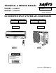
TECHNICAL & SERVICE MANUAL FILE NO. KHS0971 + CH0971 KHS1271 + CH1271 Destination: North America DC INVERTER SPLIT SYSTEM AIR CONDITIONER Indoor Model No. Product Code No. KHS0971 1 852 099 79 CH0971 1 852 330 21 KHS1271 1 852 099 80 CH1271 1 852 330 22 Indoor Unit Outdoor Model No. Product Code No. Outdoor Unit AIR CONDITIONER KHS0971 KHS1271 CH0971 CH1271 IMPORTANT These air conditioners employ new refrigerant R410A. Pay special attention when servicing the unit. REFERENCE NO.
When Transporting Important! Please Read Before Starting Be careful when picking up and moving the indoor and outdoor units. Get a partner to help, and bend your knees when lifting to reduce strain on your back. Sharp edges or thin aluminum fins on the air conditioner can cut your fingers. This air conditioning system meets strict safety and operating standards. As the installer or service person, it is an important part of your job to install or service the system so it operates safely and efficiently.
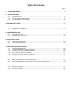
Table of Contents Page 1. OPERATING RANGE ................................................................................................................... 5 2. SPECIFICATIONS 2-1. Unit Specifications ............................................................................................................. 2-2. Major Component Specifications ....................................................................................... 2-3. Other Component Specifications .....................................
Page 10. TROUBLESHOOTING 10-1. Precautions before Performing Inspection or Repair ........................................................... 10-2. Method of Self-Diagnostics ................................................................................................. 10-3. Checking the Indoor and Outdoor Units .............................................................................. 10-4. Trouble Diagnosis of Fan Motor ...............................................................................
1. OPERATING RANGE Cooling Heating Temperature Indoor Air Intake Temp. Maximum 95 °F D.B. / 71 °F W.B. 115 °F D.B. Minimum 67 °F D.B. / 57 °F W.B. 67 °F D.B. Maximum 80 °F D.B. / 67 °F W.B. _ D.B. / _ W.B. 75 °F D.B. / 65 °F W.B. Minimum 5 Outdoor Air Intake Temp. 0 °F D.B.
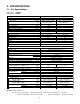
2. SPECIFICATIONS 2-1.
Indoor Unit Outdoor Unit KHS1271 CH1271 Voltage Rating Performance Total Capacity Sensible Capacity Latent Capacity Air Circulation (High) Moisture Removal (High) Electrical Rating Available Voltage Range Running Amperes Power Input Power Factor SEER HSPF Compressor Locked Rotor Amperes Fuse or Circuit Breaker Capacity Features Controls / Temperature Control Control Unit Timer Fan Speeds Airflow Direction (Indoor) 115V Single-Phase 60Hz Cooling 11,900 ( 3,000 to 11,900 ) 3.5 ( 0.9 to 3.
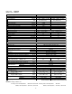
2-2. Major Component Specifications 2-2-1. Indoor Unit Indoor Unit KHS0971 Control PCB Part No. Controls Control Circuit Fuse CB-KHS0971 Microprocessor 250V 3A Remote Control Unit RCS-4HVPIS4U Fan Type Q'ty ... Dia. and Length Fan Motor Type Model ... Q'ty No. of Poles Rough Measure RPM (Cool / Heat ) Nominal Output Coil Resistance (Ambient Temp. 68 oF (20 oC)) Safety Device Type Operating Temp. Run Capacitor Flap Motor Type Model Rating Coil Resistance (Ambient Temp.
Indoor Unit KHS1271 Control PCB Part No. Controls Control Circuit Fuse CB-KHS1271 Microprocessor 250V 3A Remote Control Unit RCS-4HVPIS4U Fan Type Q'ty ... Dia. and Length Fan Motor Type Model ... Q'ty No. of Poles Rough Measure RPM (Cool / Heat ) Nominal Output Coil Resistance (Ambient Temp. 68 oF (20 oC)) Safety Device Type Operating Temp. Run Capacitor Flap Motor Type Model Rating Coil Resistance (Ambient Temp.
2-2-2. Outdoor Unit Outdoor Unit CH0971 Control PCB Part No. Controls Control Circuit Fuse CB-CH0971 Microprocessor 125V 25A Compressor Type Compressor Model / Nominal Output Compressor Oil ... Amount Pints (cc) Ohm Coil Resistance (Ambient Temp. 68 oF (20 oC)) DC Rotary (Hermetic) G4C090LU1ER / 900W FV50S ... 0.68 (320) U - V : 0.81 V - W : 0.81 W - U : 0.81 Safety Device CT (Peak current cut-off control) Compressor Discharge Temp. Control Operation cut-off control in abnormal ambient Temp.
Outdoor Unit CH1271 Control PCB Part No. Controls Control Circuit Fuse CB-CH1271 Microprocessor 125V 25A Compressor Type Compressor Model / Nominal Output Compressor Oil ... Amount Pints (cc) Ohm Coil Resistance (Ambient Temp. 68 oF (20 oC)) DC Rotary (Hermetic) G4C090LU1ER / 900W FV50S ... 0.68 (320) U - V : 0.81 V - W : 0.81 W - U : 0.81 Safety Device CT (Peak current cut-off control) Compressor Discharge Temp. Control Operation cut-off control in abnormal ambient Temp.
2-3.
3.
Outdoor Unit CH0971 CH1271 21-3/16 3-19/32 15/32 :1 5/ 16 12-7/16 10-7/16 (265) 28-11/32 (720) 11-13/32 4ID 3-19/32 Wide tube service valve dia.3/8" (9.52) 2-1/8 21-9/16 (548) Narrow tube service valve dia.1/4" (6.
4. REFRIGERANT FLOW DIAGRAM 4-1. Refrigerant Flow Diagram KHS0971 KHS1271 Outdoor Unit CH0971 CH1271 Indoor unit Outdoor unit Wide tube O.D. 3/8" (9.52 mm) Accumulator Wide tube service valve High pressure switch H.P. Muffler Compressor Indoor Unit Heat exchanger Heat exchanger 4-way valve Narrow tube O.D. 1/4" (6.
5. PERFORMANCE DATA 5-1. Temperature Charts Indoor Unit KHS0971 Outdoor Unit CH0971 Heating Characteristics High pressure at wide tube service valve psig(MPaG) Low pressure at wide tube service valve psig(MPaG) Cooling Characteristics Outdoor fan speed 159 (1.1) Low High 0°C) °F(3 ir T or A Indo 145 (1.0) .86 emp C) (27° 80°F C) (24° 75°F 131 (0.9) 117 (0.8) 77 (25) 86 (30) 95 (35) 493 (3.4) 348 (2.4) 276 (1.9) C) 30° °F( .
Indoor Unit KHS1271 Outdoor Unit CH1271 173 (1.2) Heating Characteristics High pressure at wide tube service valve psig(MPaG) Low pressure at wide tube service valve psig(MPaG) Cooling Characteristics Outdoor fan speed Low High 159 (1.1) p.86 or Indo em Air T 0°C) °F(3 C) (27° 80°F C) (24° 75°F 145 (1.0) 131 (0.9) 77 (25) 86 (30) 95 (35) 104 (40) °C) (23 3°F 7 . p C) em 20° ir T °F( A 8 r 6 ) oo 7°C Ind F(1 63° 493 (3.4) 421 (2.9) 348 (2.4) 276 (1.
5-2. Air Throw Distance Charts Indoor Unit Cooling KHS0971 Room air temp. : Fan speed : 80°F (26.7°C) High Horizontal distance (ft.) 0 5 10 15 20 25 30 Axis air velocity (ft./sec.) Vertical distance (ft.) 0 5 10 15 : Flap angle 0°, : Flap angle 30°, Heating Room air temp. : Fan speed : : Axis air velocity 0° : Axis air velocity 30° 70°F (21.1°C) High Horizontal distance (ft.) 0 5 10 15 20 25 Axis air velocity (ft./sec.) Vertical distance (ft.
Indoor Unit Cooling KHS1271 Room air temp. : Fan speed : 80°F (26.7°C) High Horizontal distance (ft.) 0 5 10 15 20 25 30 Axis air velocity (ft./sec.) Vertical distance (ft.) 0 5 10 15 : Flap angle 0°, : Flap angle 30°, Heating Room air temp. : Fan speed : : Axis air velocity 0° : Axis air velocity 30° 70°F (21.1°C) High Horizontal distance (ft.) 0 5 10 15 20 25 Axis air velocity (ft./sec.) Vertical distance (ft.
6. ELECTRICAL DATA 6-1. Electrical Characteristics Indoor Unit KHS0971 Outdoor Unit CH0971 Cooling Indoor Unit Fan Motor Performance at Rating conditions Rating conditions: Running amp. Power input Indoor air temperature: Outdoor air temperature: A W 0.45 45 Outdoor Unit Fan Motor + Compressor 115V Single-phase 60Hz 7.15 710 Complete Unit 7.6 755 80°F (26.7°C) D.B. / 67°F (19.4°C) W.B. 95°F (35°C) D.B. Heating Indoor Unit Fan Motor Performance at Rating conditions Rating conditions: Running amp.
6-2. Electric Wiring Diagrams KHS0971 KHS1271 To avoid electrical shock hazard, be sure to disconnect power before checking, servicing and/or cleaning any electrical parts.
Outdoor Unit CH0971 CH1271 To avoid electrical shock hazard, be sure to disconnect power before checking, servicing and/or cleaning any electrical parts.
7. INSTALLATION INSTRUCTIONS 7-1. Installation Site Selection 7-1-1. Indoor Unit WARNING To prevent abnormal heat generation and the possibility of fire, do not place obstacles, enclosures and grilles in front of or surrounding the air conditioner in a way that may block air flow. 6" (15 cm) min. 2" (5 cm) min. 2" (5 cm) min. Front View AVOID: Fig. 1 direct sunlight. nearby heat sources that may affect performance of Tubing length (L) INDOOR UNIT the unit.
NO 7-1-2. Outdoor Unit Exhaust fan Hot air AVOID: Heat source heat sources, exhaust fans, etc. (Fig. 4) damp, humid or uneven locations. Outdoor unit DO: choose a place as cool as possible. choose a place that is well ventilated. Fig. 4 allow enough room around the unit for air intake/ Obstacle above block, 4" 1' 4" (10 Air intake 40 cm) beams or equal), a Min. 2" (5 cm) minimum of 4" (10 cm) above ground level to reduce humidity and protect the unit against Min.
7-2. Recommended Wire Length and Diameter Regulations on wiring diameter differ from locality to locality. For field wiring requirements, please refer to your local electrical codes. Carefully observe these regulations when carrying out the installation. Table 2 lists recommended wire lengths and diameters for power supply systems. NOTE Refer to the wiring system diagram (Fig. 6) for the meaning of (A), (B) and (C) in Table 2.
7-3. Remote Control Unit Installation Position The remote control unit can be operated from either a non-fixed position or a wall-mounted position.
7-4. How to Test Run the Air Conditioner After turning on power to the air conditioner, use the remote controller and follow the steps below to conduct the test run. (1) Set the remote controller in Test Run mode. (Fig. 8a) a) Press and hold the ION button. b) Then press and hold the 1HR TIMER button. c) At the same time, press the ACL (reset) button once. Use a pointed object such as the tip of a pen to press the ACL button.
Grille Air intake grille 7-5. Remove the Grille to Install the Indoor Unit Basically, these models can be installed and wired without removing the grille. If access to any internal part is needed, follow the steps as given below. CAUTION Fig. 9a Be sure to wear work gloves during installation to avoid being cut by the sharp aluminum fins of the heat exchanger. How to remove the grille (1) Grasp both ends of the air intake grille, and remove it by opening towards the front and pulling towards you. (Fig.
8. MAINTENANCE Tab 8-1. Address Setting of the Remote Control Unit The address can be set in order to prevent interference between remote controllers when two indoor units are installed near each other. The address is normally set to "A." To set a different address, it is necessary to change the address on the second remote controller. Fig. 13 NOTE Once changed, you cannot restore the original address setting of the air conditioner. (1) Switch on the power source.
8-2. Disconnecting and Connecting Positive Connector for Outdoor Unit One of the two types of connectors illustrated at left is used. Their basic structure is the same for each. How to Disconnect Hold the resin connector cover, and pull the connector off. You cannot disconnect the connector by pulling the wire since it is locked inside. Always hold the cover to disconnect. (See illustration at left.) For the connector without the resin cover, push the lock in the direction of "2" while pulling it off.
9. FUNCTIONS 9-1. Operation Functions Emergency operation SENSOR DRY Emergency operation is available when the remote controller malfunctions, has been lost, or otherwise cannot be used. During DRY operation, the system adjusts the room temperature and fan speed according to the conditions in the room, in order to maintain a comfortable room environment. SENSOR DRY operation • DRY operation is as shown in the figure below.
HIGH POWER NIGHT SETBACK This function acts to raise the power but keeps the AC system in the same operating mode. This function is set with the HIGH POWER button on the remote controller. (It can be set regardless of the temperature and fan speed settings.) When NIGHT SETBACK operation is set, the temperature and fan speed settings will be adjusted automatically to allow comfortable sleep. When NIGHT SETBACK operation is set, " mark" appears on the remote controller.
9-2. Protective Functions Overload prevention during heating Cold-air prevention during heating Indoor heat exchanger temperature °F(°C) During HEAT operation, the temperature of the indoor heat exchanger is used to control the frequency and lessen the load on the compressor before the protective device is activated. Approx. 127 (53) During heating, the fan speed is set to "LL" (very low) or stopped. As the temperature of the indoor heat exchanger rises, the fan speed is changed to the set speed.
Defrost detection and release CT (Peak current cut-off control) • This function prevents the circuit breaker or fuse from operating to open the circuit. This function works when electrical current has increased due to an increase in the cooling / heating load, or to a decrease in the power supply voltage. In these cases, operation frequency is reduced or operation is interrupted automatically to control the electrical current for operation.
10. TROUBLESHOOTING 10-1. Precautions before Performing Inspection or Repair After checking the self-diagnostics monitor, turn the power OFF before starting inspection or repair. High-capacity electrolytic capacitors are used inside the outdoor unit controller (inverter). They retain an electrical charge (charging voltage DC 310V) even after the power is turned OFF, and some time is required for the charge to dissipate. Be careful not to touch any electrified parts before the controller LED (red) turns OFF.
(1) Self-diagnostics Lamps INDOOR UNIT (1) OPERATION lamp (2) TIMER lamp (3) QUIET lamp ION lamp OPERATION button REMOTE CONTROL receiver Since the indications cover various units, the corresponding parts listed below may not be present in some models. .... OFF Indication on indoor unit Quiet (3) Timer (2) Operation (1) .... Blinking ....
(2) If the self-diagnostics function fails to operate Check the indoor unit. • No indicators illuminate and the indoor fan does not rotate. • Check the power voltage. Blown Is the fuse blown? Normal Replace the circuit board or the fuse. Replace the controller.
10-3. Checking the Indoor and Outdoor Units (1) Checking the indoor unit No. Control 1 Check items (unit operation) • The rated voltage must be present between inter-unit wirings 1 and 2. • Connect a 5 k ohm resistor between inter-unit wirings 2 and 3. When the voltage at both ends is measured, approximately 12 to 15V DC must be output and the multimeter pointer must bounce once every 8 seconds.
10-4. Trouble Diagnosis of Fan Motor 10-4-1. Outdoor Fan Motor This outdoor DC fan motor contains an internal control PCB. Therefore, it is not possible to measure the coil resistance, and the following procedure should be used to check the motor. Perform the trouble diagnosis by Test Run mode described on Installation Instructions. Important: (A) Turn OFF the power before connecting or disconnecting the motor connectors.
10-5. Noise Malfunction and Electromagnetic Interference An inverter A/C operates using pulse signal control and high frequencies. Therefore, it is susceptible to the effects of external noise, and is likely to cause electromagnetic interference with nearby wireless devices. A noise filter is installed for ordinary use, preventing these problems. However, depending on the installation conditions, these effects may still occur. Please pay attention to the points listed below.
11. CHECKING ELECTRICAL COMPONENTS Ground wire 11-1. Measurement of Insulation Resistance Clip The insulation is in good condition if the resistance exceeds 1M ohm. Probe 11-1-1. Power Supply Cord Insulation tester Clamp the grounding wire of power cord with the lead clip of the insulation resistance tester and measure the resistance by placing a probe on either of the two power wires. (Fig. 1) Then also measure the resistance between the grounding and other power terminals. (Fig. 1) Fig.
11-2. Checking Continuity of Fuse on PCB Ass'y Fuse Remove the PCB Ass'y from the electrical component box. Then pull out the fuse from the PCB Ass'y. (Fig. 5) Check for continuity using a multimeter as shown in Fig. 6. PCB Ass'y Fig. 5 Fuse Fig.
12. REFRIGERANT R410A: SPECIAL PRECAUTIONS WHEN SERVICING UNIT 12-1. Characteristics of New Refrigerant R410A 12-1-1. What is New Refrigerant R410A? R410A is a new refrigerant that contains two types of pseudo-non-azeotropic refrigerant mixture. Its refrigeration capacity and energy efficiency are about the same level as the conventional refrigerant, R22. 12-1-2. Components (mixing proportions) HFC32 (50%) / HFC125 (50%) 12-1-3.
12-2. Checklist before Servicing Use a clutch-type flare tool for R410A or the conventional flare tool. Note that sizes of the resultant flares differ between these two tools. Where a conventional flare tool is used, make sure to observe A Specification (amount of extrusion) by using the flare spacer. Specification A Diameter of tube D Flare tool for R410A Conventional flare tool (for R22) Dia.3/8" (9.52 mm) 0 to 0.0196" 0.0472" Dia.1/2" (12.7 mm) (0 to 0.5 mm) (1.2 mm) Dia.1/4" (6.35 mm) Dia.
12-3. Tools Specifically for R410A For servicing, use the following tools for R410A Tool Distinction Tool Name Gauge manifold Charging hose Gas leak detector Refrigerant cylinder Charging cylinder Refrigerant recovery unit Tools specifically for R410A Vacuum pump with anti-reverse flow (*1) (Solenoid valve-installed type, which prevents oil from flowing back into the unit when the power is off, is recommended.) Vacuum pump (*2)...can be used if the following adapter is attached.
12-5. In Case of Compressor Malfunction CAUTION Should the compressor malfunction, be sure to make the switch to a replacement compressor as quickly as possible. Use only the tools indicated exclusively for R410A. Specifically for R410A." See "12-3. Tools 12-5-1. Procedure for Replacing Compressor (1) Recovering refrigerant Any remaining refrigerant inside the unit should not be released to the atmosphere, but recovered using the refrigerant recovery unit for R410A.
(5) Recharging Configuration and characteristics of cylinders Be sure to charge the specified amount of refrigerant in liquid state using the service port of the wide tube service valve. The proper amount is listed on the unit's nameplate. Valve When the entire amount cannot be charged all at once, charge gradually while operating the unit in Cooling Operation. CAUTION Liquid Never charge a large amount of liquid refrigerant at once to the unit. This may cause damage to the compressor.
12-6. In Case Refrigerant is Leaking CAUTION Never attempt to charge additional refrigerant when refrigerant has been leaking from the unit. Follow the procedure described below to locate points of leaks and carry out repairs, then recharge the refrigerant. (1) Detecting Leaks Use the detector for R410A to locate refrigerant leak points.
12-7. Charging Additional Refrigerant 12-7-1. When Tubes are Extended Observe the proper amount of refrigerant as stated in this service manual or the installation manual that came with the indoor unit. Charge additional refrigerant in liquid state only. CAUTION Never charge additional refrigerant if refrigerant is leaking from the unit. Follow instructions given in "12-6. In Case Refrigerant is Leaking" and completely carry out repairs. Only then should you recharge the refrigerant. 12-8.
APPENDIX INSTRUCTION MANUAL KHS0971 + CH0971 KHS1271 + CH1271 (OI-852-6-4180-802-00-0) 50
01_KHS0971_EN.fm Page 2 Tuesday, September 27, 2005 2:53 PM Features This air conditioner is an inverter type unit that automatically adjusts capacity as appropriate. Details on these functions are provided below; refer to these descriptions when using the air conditioner. • Microprocessor Controlled Operation The interior compartment of the remote control unit contains several features to facilitate automatic operation, easy logically displayed for easy use.
01_KHS0971_EN.fm Page 3 Tuesday, September 27, 2005 2:53 PM Contents Page Features ...................................................................................................................2 Product Information..................................................................................................3 Alert Symbols...........................................................................................................3 Installation Location ................................................
01_KHS0971_EN.fm Page 4 Tuesday, September 27, 2005 2:53 PM Installation Location • We recommend that this air conditioner be installed properly by qualified installation technicians in accordance with the Installation Instructions provided with the unit. Before installation, check that the voltage of the electric supply in your home or office is the same as the voltage shown on the nameplate.
01_KHS0971_EN.fm Page 5 Tuesday, September 27, 2005 2:53 PM Names of Parts Air intakes INDOOR UNIT Air outlet Remote control unit Drain hose Refrigerant tubes OUTDOOR UNIT Air outlet NOTE This illustration is based on the external view of a standard model. Consequently, the shape may differ from that of the air conditioner which you have selected. This air conditioner consists of an indoor unit and an outdoor unit. You can control the air conditioner with the remote control unit.
01_KHS0971_EN.fm Page 6 Tuesday, September 27, 2005 2:53 PM Unit Display and Operation Button INDOOR UNIT IMPORTANT Avoid using radio equipment such as mobile phone near (within 4 ft.) the remote control receiver. Some radio equipment may cause malfunction of the unit. QUIET OPERATION lamp TIMER lamp QUIET lamp ION lamp OPERATION button If the trouble happens, disconnect power and restart the air conditioner after a few minutes.
01_KHS0971_EN.fm Page 7 Tuesday, September 27, 2005 2:53 PM Remote Control Unit (Display) Displayed when transmitting data Displayed when indoor unit sensor is in use Displayed when setting temperature Displayed when temperature is shown Displayed when setting timer Displayed when the time display is set to 12-hour time. Symbols (1) Operation mode AUTO ......................................... HEAT .......................................... MILD DRY ..................................
01_KHS0971_EN.fm Page 8 Tuesday, September 27, 2005 2:53 PM Remote Control Unit Sensor Transmitter (Cover closed) Display ON/OFF operation button ION button 1 HR. TIMER button Temperature setting buttons (TEMP.
01_KHS0971_EN.fm Page 9 Tuesday, September 27, 2005 2:53 PM Remote Control Unit (continued) Temperature setting buttons (TEMP.) Press the button to increase the set temperature. Press the button to reduce the set temperature. The temperature setting changes by 1 °C or 2 °F each time one of the TEMP. buttons is pressed. QUIET button : When you press this button, the fan rotates slower than the fan speed setting to provide a quieter operating sound.
01_KHS0971_EN.fm Page 10 Tuesday, September 27, 2005 2:53 PM Remote Control Unit (continued) SENSOR button NOTE Temperature Display Selector button Time Display Selector button ACL button (ALL CLEAR) ADDRESS switch When you press this button (use a small-tipped object such as a ballpoint pen), the mark will appear at the display. And the room temperature is detected by the sensor which is built into the indoor unit and the air conditioner is controlled accordingly.
01_KHS0971_EN.fm Page 11 Tuesday, September 27, 2005 2:53 PM Using the Remote Control Unit (continued) How to Use the Remote Control Unit When using the remote control unit, always point the unit’s transmitter head directly at the air conditioner’s receiver.
01_KHS0971_EN.fm Page 12 Tuesday, September 27, 2005 2:53 PM Operation with the Remote Control Unit 1. Automatic Operation This unit automatically switches between cooling operation and heating operation according to the difference between the room temperature and the temperature setting. STEP 2 STEP 1 NOTE Check that the circuit breaker on the power panel is turned on.
01_KHS0971_EN.fm Page 13 Tuesday, September 27, 2005 2:53 PM Operation with the Remote Control Unit (continued) 2. Manual Operation STEP 2 STEP 3 STEP 1 STEP 4 STEP 5 NOTE Check that the circuit breaker on the power panel is turned on. If the automatic operation settings of the unit do not meet your needs, press the setting buttons as described below and change the settings as desired. STEP 1 Press the MODE selector button and select the desired mode.
01_KHS0971_EN.fm Page 14 Tuesday, September 27, 2005 2:53 PM Operation with the Remote Control Unit (continued) NOTE • Choose the best position in the room for the remote control unit, which also acts as the sensor for room comfort and transmits the operating instructions. Once you’ve found this best position, always keep the remote control unit there. • This appliance has a built-in 5-minute time delay circuit to ensure reliable operation.
01_KHS0971_EN.fm Page 15 Tuesday, September 27, 2005 2:53 PM Operation with the Remote Control Unit (continued) 5. Night Setback Mode Night Setback Mode is used for saving energy. Press the NIGHT SETBACK button while operation. The mark appears in the display. To release the night setback function, press the NIGHT SETBACK button again. A.
01_KHS0971_EN.fm Page 16 Tuesday, September 27, 2005 2:53 PM Operation with the Remote Control Unit (continued) 6. QUIET Mode QUIET Mode is used to reduce the fan sound of the indoor unit. Press the QUIET button. The mark appears in the display. To cancel, press QUIET button again. • • In QUIET Mode, the fan rotates at a slower speed than the fan speed setting. If the unit is already operating with a very low airflow, the fan sound may not change even if the QUIET button is pressed. 7.
01_KHS0971_EN.fm Page 17 Tuesday, September 27, 2005 2:53 PM Special Remarks ‘‘DRY’’ ( ) Operation How it works? • • • Heating ( Once the room temperature reaches the level that was set, the unit’s operation frequency is changed automatically. During DRY operation, the fan speed automatically runs at lower speed for providing a comfortable breeze. ‘‘DRY’’ operation is not possible if the indoor temperature is 59 °F or less.
01_KHS0971_EN.fm Page 18 Tuesday, September 27, 2005 2:53 PM Setting the Timer NOTE 1. How to set the present time In the descriptions below, the following settings are used for the temperature and time indicator selector button on the bottom front section of the remote control. • Temperature: °F • Time: AM, PM (Example) To set to 10:30 pm. Operation 2. How to set the OFF time 18 Indication 1. Press the CLOCK button once if the time indicator is not flashing. The time indication alone flashes. 2.
01_KHS0971_EN.fm Page 19 Tuesday, September 27, 2005 2:53 PM Setting the Timer (continued) 3. How to set the ON time (Example) To start operation at 7:10 am. Operation 4. How to set DAILY ON/OFF REPEAT timer Indication 1. Press the ON TIME setting button once. The timer indication is displayed, and the present ON time is shown. 2. Press the Advance, Return ( , ) button until AM 7:10 is displayed. The timer indication blinks. The time can be set in 10-minute increments.
01_KHS0971_EN.fm Page 20 Tuesday, September 27, 2005 2:53 PM Using the 1-Hour OFF Timer 1. 1-Hour OFF Timer This function causes the unit to operate for one hour and then stop, regardless of whether the unit is on or off when this button is pressed. The indicator in the display indicates that this function is operating. Setting procedure: Regardless of whether the unit is operating or stopped, press the 1 HR. TIMER button. appears in the display.
01_KHS0971_EN.fm Page 21 Tuesday, September 27, 2005 2:53 PM Adjusting the Airflow Direction 1. Horizontal The horizontal airflow can be adjusted by moving the vertical vanes with your hands to the left or right. When the humidity is high, the vertical vanes should be in the front position during the cooling or dehumidifying operation. If the vertical vanes are positioned all of the way to the right or left, condensation may begin to form around the air vent and drip down. CAUTION 2.
01_KHS0971_EN.fm Page 22 Tuesday, September 27, 2005 2:53 PM Operation without the Remote Control Unit INDOOR UNIT If you have lost the remote control unit or it has trouble, follow the steps below. When the air conditioner is not running Each time the OPERATION button is pressed, the type of operation conducted is indicated by the changing color of the OPERATION lamp. Press the button and select the lamp color that suits your preference for operation.
01_KHS0971_EN.fm Page 23 Tuesday, September 27, 2005 2:53 PM Care and Cleaning (continued) Anti-Mold Filter How to remove the anti-mold filter The anti-mold filter behind the air intake grille should be checked and cleaned at least once every two weeks. 1. Grasp both ends of the air intake grille, and remove it by opening towards the front and pulling towards you. Air intake grille 2. Remove the anti-mold filter attached to the rear of the air intake grille.
01_KHS0971_EN.fm Page 24 Tuesday, September 27, 2005 2:53 PM Care and Cleaning (continued) Air Clean Filter The air clean filter removes dust and dirt from the air, and reduces odors and smoke from tobacco. This air clean filter cannot remove harmful gases or vapors nor ventilate air in the room. You must open doors or windows frequently when you use gas or oil heating appliances. Otherwise there is a risk of suffocation in extreme cases.
01_KHS0971_EN.fm Page 25 Tuesday, September 27, 2005 2:53 PM Troubleshooting If your air conditioner does not work properly, first check the following points before requesting service. If it still does not work properly, contact your dealer or service center. Trouble Possible Cause Air conditioner does not run at all. Remedy 1. Power failure. 1. Restore power. 2. Leakage circuit breaker tripped. 2. Contact service center. 3. Line voltage is too low. 3. Consult your electrician or dealer. 4.
For Parts Service Contact SANYO Fisher Service Company A Division of SANYO North America Corporation 1165 Allgood Road, Suite 22, Marietta, GA 30062 U.S.A. Sanyo Canada Inc. 1-300 Applewood Crescent, Concord, Ontario L4K 5C7, CANADA Aug.