
User Guide


Installation Sheet
RDM-DC DC Dimmer Module
1920 W, 0-10 VDC
The RDM-DC DC Dimmer Module is a 1920 W module used for the dim-
ming of fluorescent ballast loads. It uses a 0 to 10 VDC current sinking for
use with four-wire ballasts. It is designed for use with the RDA series of
enclosures, in an AMX Lighting™ modular digital dimming system. The
module’s 120 and 277 VAC ratings are CE, UL, and C-UL approved.
RDM-DC UL and C-UL Ratings
• 120 VAC, 50/60 Hz, 1920 W
• 277 VAC, 50/60 Hz, 1920 W
• Control Out: 50 mA, 12 VDC sinking
Suggested Dimmed Loads
• Four-wire dimmable ballasts, like Advance Transformer Mark VII™ or
the Energy Savings SuperDim™ series
Specifications
• Dimensions (HW): 10" x 2.75" (25.4 cm x 6.99 cm)
• Non-phase dependant
• Use wires rated at 75°C (167°F)
• Torque terminals to 20 in-lbs. (2.3 N/M)
• Max. wire size: 10 AWG (4 mm²)
• Wire stripping length: 0.28" (7 mm)
• Weight: 2.3 lbs. (1.043 kg)
• BTU/hr: 150
• Control current: 125 mA @ 12 VDC
Caution: Pre-Installation Notes
• All Class 1 wiring must be connected to proper terminals.
• All control wiring must be connected to proper terminals.
• Disconnect power while installing or connecting the unit.
• Keep top and bottom air vents clear at all times.
• Use low-voltage wires with a 300 volt rating or greater.
• Use field installed copper conductors.
• All electrical ratings are for continuous duty.
• For indoor use only.
• Test loads for shorts before connecting.
• This module may require extra power from the AXlink connection or an
external power supply connected to the control card.
Connecting the RDM-DC to the AMX Lighting Master
Lighting Application Drawings
Warning: Failure to ground the ballast may cause ballast
failure
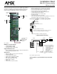
FIG. 1 RDM-DC
Low-voltage control
wiring: 4-pin
Relay
+ out (LV)
- out (LV)
Line in
Load
High
Low-voltage
voltage
connector to AMX
Lighting master
controller
Mounting
points
Fuses
out
FIG. 2 Connecting the RDM-DC and AMX Lighting Master
FIG. 3 RDM-DC application wiring
Pin 4 (GND)
Pin 3 (RLY)
Pin 2 (DIM)
Pin 1 (+12 V)
RDM-DC 4-pin module connector
1 (+)
2 (DIM)
3 (-)
GND
4-pin plug from RDM series module
Note: The 4-pin plugs from the module connector to the 4-pin
connector on the master (black plug cover facing up).
Ballast
Florescent
Neutral
Line in (HOT)
Load
Neutral
+
-
Circuit breaker
panel
Ballast
The fuses protect the dimming
circuit from a low impedance load.
• The fuse will blow if it were
incorrectly wired
• Catastrophic ballast failure
• Reversing switched and
dimmed circuits
• Reversing dimmed and
line circuits.
The dimmed output must be
connected to a high impedance
load.