
User's Manual
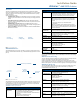
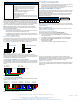
Table Of Contents

For full warranty information, refer to the AMX Instruction Manual(s) associated with your Product(s).
2/08
©2008 AMX. All rights reserved. AMX and the AMX logo are registered trademarks of AMX.
AMX reserves the right to alter specifications without notice at any time.
3000 RESEARCH DRIVE, RICHARDSON, TX 75082 • 800.222.0193 • fax 469.624.7153 • technical support 800.932.6993 • www.amx.com
93-5172-04 REV: A
Anterus Tags - Internal Battery
An internal lithium battery powers the Anterus RFID Tags. Each RFID Tag will, for the
duration of its life, transmit a Radio Frequency (RF) signal at a pre-set time interval.
The Tag life is estimated at 5 years at a transmission time interval of approximately
1.5 seconds. The life span of the Tag ends when the battery life is exhausted. Battery
status can be inferred by interrogating the internal Tag Age Counter Value.
Note: The internal lithium battery in the Anterus RFID Tags cannot be replaced.
Additional and replacement tags are available from AMX. Contact your customer
service representative for details.
Anterus Tags - Mounting/Installation
• ANT-TAG Tags can be mounted on a variety of non-metallic items. Where per-
manent fixing is required, VHB double-sided tape is used.
• ANT-BDG Tags can be mounted on a variety of items. Where permanent fixing
is required VHB double-sided tape is used; otherwise, the tags may be worn on
a necklace or clipped to clothing.
Anterus Tags - Antenna Orientation
For optimal RF reception, the tags should be mounted in the same orientation as the
antenna used on the reader (FIG. 3). The system will still function if the orientations
do no match: however, the range will be decreased. It is best to mount all tags in the
same orientation, no matter if it matches the orientation of the antenna.
Note: ANT-BDG ID Badge tags are typically worn on a necklace or clipped to
clothing, which typically results in a vertical antenna orientation. There is a horizontal
orientation for the ANT-BDG Tags, but it is typically reserved for installations that use
the ANT-BDG Tags as windshield-mounted vehicle tags.
Connecting the ANT-RDR To a NetLinx Master
The ANT-RDR uses a single 4-pin captive-wire AxLink port to connect the ANT-RDR
to a NetLinx Master, and (optionally) to other ANT-RDRs. To connect the ANT-RDR
to the NetLinx Master via AxLink, install the AXlink data/power bus wiring as shown
in FIG. 4.
Connecting Additional ANT-RDRs
To connect additional ANT-RDRs to create a RFID Reader Network Group, follow the
standard AxLink bus wiring (FIG. 5).
Preparing And Connecting Captive Wires
1. Strip 0.25 inch of wire insulation off all wires.
2. Insert each wire into the appropriate opening on the connector according to the
wiring diagrams and connector types described in this section.
3. Tighten the screws to secure the wires. Do not tighten the screws excessively;
doing so may strip the threads and damage the connector.
Assigning the ANT-RDR Device Address
The ANT-RDR sets its unique AXLink address via the 8-position DIP switch located
on the rear panel (see FIG. 2). AXLink addresses must be in the range of 1 to 255
(address 0 belongs to the Master).
The AXLink address distinguishes a device on the AXLink bus from other devices.
Care should be taken by the system integrator not to assign duplicate AXLink
addresses to multiple devices.
Note: The device number takes effect only upon power-up. If you later change the
device number, remove and reconnect the AXlink connector to enter the new device
number into memory.
Anterus Tag Addressing
Use the ANT-RDR’s built-in web console to add each Anterus Tag to the system,
assigning each one a unique Tag ID.
Accessing the Configuration Manager
The default IP Address for the ANT-RDR is 192.XXX.XXX.XXX.
From any PC that has access to the LAN that the ANT-RDR resides on:
1. Open a web browser and type the IP Address of the target ANT-RDR in the
browser’s Address Bar.
2. Press Enter to access the Configuration Manager for the specified device.
3. If prompted for a User Name and Password (FIG. 6), enter the defaults:
• Default User Name = Admin
• Default Password = 1988
4. The initial view is the RFID Configuration Manager page (FIG. 6).
The options in this page allow you to view and configure the Anterus system
(Readers and tags) as a whole (Global Settings), as well as view and configure each
ANT-RDR Reader in the system individually. Configuration options include naming
each ANT-RDR, and managing each of the RFID Tags in the system.
Additional Documentation
Refer to the Anterus RFID Solution Operation/Reference Guide (available online at
www.amx.com) for additional information on installing and configuring the ANterus
RFID Solution.
ANT-TAG / ANT-BDG Specifications (Cont.)
Certifications: This device complies with Part 15 of the FCC Rules. Oper-
ation is subject to the following two conditions:
• This device may not cause harmful interference, and,
• This device must accept any interference received,
including interference that may cause undesired
operation.
The following standards applied in accordance with
Article 5 of the directive, 1999/5/EC:
• EN 300 220-1 V1.2.1 (1997-11)
• ETS 300 683 (1997-03)
Any modification of this device without the express consent
of the manufacturer could void the user authority to operate
the equipment.
FIG. 3
ANT-RDR / ANT-TAG Antenna Orientation
FIG. 4 AXlink data/power connections
FIG. 5 Connecting Additional ANT-RDRs
ANT-RDR ANT-TAG
Vertical Orientation Horizontal Orientation
ANT-RDR ANT-TAG
PWR
AXP
AXM
GND
ANT-RDRNetLinx Master
PWR
AXP
AXM
GND
PWR
AXP
AXM
GND
ANT-RDRNetLinx Master
PWR
AXP
AXM
GND
PWR
AXP
AXM
GND
PWR
AXP
AXM
GND
PWR
AXP
AXM
GND
ANT-RDRANT-RDR ANT-RDR
Device DIP Switch Settings
Position1234 5 6 7 8
Value 1248163264 128
FIG. 6
RFID Configuration Manager - Main Page (initial view)
1 2 3 4 5 678
ON
Example: Device #128