
User's Manual
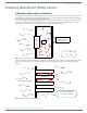
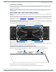
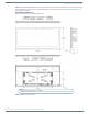
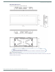

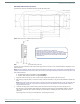
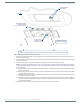
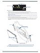
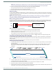
Table Of Contents
- MODERO X® SERIES TOUCH PANELS - INSTALLATION & HARDWARE REFERENCE MANUAL
- Modero X Series (G4) Touch Panels
- MXT/D-2000XL-PAN - 20.3" X Series Panels
- MXT/D-1900L-PAN - 19.4" X Series Panels
- MXT/D-1000 - 10.1" X Series Panels
- MXT/D-700 - 7" X Series Panels
- MXD-430 - 4.3” X Series Panels
- Installing Tabletop (MXT) Panels
- Installing Wall-Mount (MXD) Panels
- A Note About Wall and Rack Installation
- MXD-2000XL-PAN / MXD-1900L-PAN Installation
- MXD-1000/ MXD-700 Installation
- MXD-430 Installation
- Upgrading Firmware
- Troubleshooting

Installing Wall-Mount (MXD) Panels
48
Modero X® Series Touch Panels - Installation & Hardware Reference Manual
4. Remove any knockouts as needed on either long dimension of the Backbox to facilitate incoming wiring and pull the wiring
through the resultant holes.
5. Push the Backbox into the wall opening. Insure that the locking tabs lie flush against the Backbox, and that the Backbox goes
freely into the opening.
6. Extend the locking tabs on the sides of the Backbox by tightening the screws inside the box until snug.
NOTE: The maximum recommended torque to screw in the locking tabs on the plastic Backbox is 5 IN-LB [56 N-CM]. Applying
excessive torque while tightening the tab screws, such as with powered screwdrivers, can strip out the locking tabs or damage
the plastic Backbox.
Not all of the tabs must be extended to lock the Backbox in place, but extending a minimum of the top and bottom tabs is
highly recommended.
Apply enough pressure to the screw head to keep the box flush with the wall: this ensures that the locking tabs will tighten
up against the inside of the wall.
The Backbox is clear to allow visual confirmation that the tabs have been extended and are gripping the wall, as well as in
assisting with removal if necessary.
For additional strength, #4 mounting screws (not included) may be secured through circular holes located at the left and
right sides of the MXD-2000XL-PAN (see FIG. 31). In order to prevent damage to the touch panel, make sure that these
are flush with the Backbox.
7. Insert each connector into its corresponding location along the back of the device (FIG. 32).
FIG. 31
MXD-1900L-PAN Backbox installation (Landscape)
4X Installation Clamp
for Wall Thickness
.37 [12.01] to .98 [25.0]
Cables Routed to
Wall Opening
8X Knock Outs
Remove For Cable
Routing As Needed
Mounting screws
placement (optional)
Wall
Note:
Additional detailed installation and product drawings are available to view/download at www.amx.com