
User's Manual
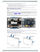
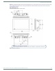
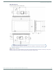
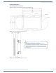
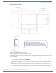
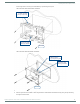
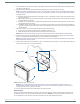
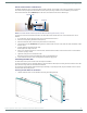
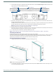
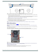
Table Of Contents
- MODERO X® SERIES TOUCH PANELS - INSTALLATION & HARDWARE REFERENCE MANUAL
- Modero X Series (G4) Touch Panels
- MXT/D-2000XL-PAN - 20.3" X Series Panels
- MXT/D-1900L-PAN - 19.4" X Series Panels
- MXT/D-1000 - 10.1" X Series Panels
- MXT/D-700 - 7" X Series Panels
- MXD-430 - 4.3” X Series Panels
- Installing Tabletop (MXT) Panels
- Installing Wall-Mount (MXD) Panels
- A Note About Wall and Rack Installation
- MXD-2000XL-PAN / MXD-1900L-PAN Installation
- MXD-1000/ MXD-700 Installation
- MXD-430 Installation
- Upgrading Firmware
- Troubleshooting

Installing Wall-Mount (MXD) Panels
60
Modero X® Series Touch Panels - Installation & Hardware Reference Manual
3. With a stout, strong point (a push pin or straightened paper-clip, for example), carefully press into the access holes in either
end of the molding until the snap is disconnected.
To facilitate the disconnection, grasp the bottom of the panel (Landscape) or right side (Portrait) and pull gently outward until
the side of the panel is free of the snap. Use your other hand to hold stable the front of the touch panel.
NOTE: Always pull on the frame of the touch panel. NEVER pull on the glass edge.
4. When the first side is free, repeat the process with the other.
5. With the edge of the touch panel free, carefully lift up and out (Landscape) or to the left and out (Portrait) to remove the touch
panel from the Backbox. Be careful not to pull on the cables or connectors.
6. To reattach the panel to its Backbox, repeat the installation procedure.
NOTE: For further information, refer to the video available at www.amx.com (go to Newsroom > Videos > Touch Panels).
MXD-430 Installation
Detailed specifications drawings for the MXD-430 are available to download from www.amx.com.
NOTE: Refer to A Note About Wall and Rack Installation on page 42 for important notes on thermal concerns with Wall and Rack
Installations.
The MXD-430 may be installed directly into a solid surface environment, using either solid surface screws or the included locking
tabs for different mounting options.
Once installed, the MXD-430 is contained within a clear outer housing known as the Backbox (FIG. 23).
This Backbox is removed before installing the device into a wall or when using the optional Rough-In Box accessory (FG039-19).
NOTE: For typical mounting surfaces, such as drywall, use the locking tabs as the primary method for securing the Backbox to the
surface. For thin walls or solid surfaces, use mounting screws (not included).
Installing the MXD-430 Into a Wall
The backbox has two locking tabs (one on each side) to help lock the backbox to the wall (see FIG. 52).
These locking tabs are only extended AFTER the backbox is inserted into the wall.
FIG. 51
Bottom View (Landscape) or Right-Side View (Portrait) of the MXD-700 showing access holes in molding
FIG. 52 MXD-430 Backbox
Access hole Access hole
Panel (surface)
#5 #5
Locking tab
Locking tab