
User's Manual
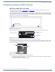
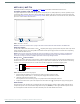
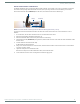


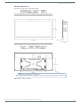
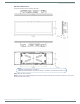
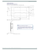
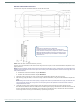
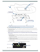
Table Of Contents
- MODERO X® SERIES G5 TOUCH PANELS - INSTALLATION & HARDWARE REFERENCE MANUAL
- Modero X Series G5 Touch Panels
- MXT/D-2001-PAN - 20.3" X Series G5 Panels
- MXT/D-1901-PAN - 19.4" X Series G5 Panels
- MXT/D-1001 - 10.1" X Series G5 Panels
- MXT/D-701 - 7" X Series G5 Panels
- Installing Tabletop (MXT) Panels
- Installing Wall-Mount (MXD) Panels
- A Note About Wall and Rack Installation
- MXD-2001-PAN / MXD-1901-PAN Installation
- MXD-1001 / MXD-701 Installation
- Appendix: Troubleshooting

Installing Tabletop (MXT) Panels
31
Modero X® Series G5 Touch Panels - installation & Hardware Reference Manual
Installing Tabletop (MXT) Panels
MXT-2001-PAN / MXT-1901-PAN
Detailed specifications drawings for the MXT-2001-PAN and MXT-1901-PAN are available to download from www.amx.com.
Connector Locations - MXT-2001-PAN / MXT-1901-PAN
Two Type A USB ports are located on the rear right corner of the panel (FIG. 14). USB peripherals (i.e. mouse, keyboard) may be
connected to either of the two USB ports on the rear of the device. Updates to the device’s firmware can also made via the USB
ports (see the Modero G5 Configuration and Programming Guide for details). Note that FIG. 14 shows the MXT-1901-PAN, but the
USB ports are in a similar location on the MXT-2001-PAN.
The Power and Ethernet connectors, as well as an additional USB port are located on the bottom of the device (FIG. 15).
NOTE: Refer to the Power via 13.5V section on page 32 for details on wiring a power connection.
The underside USB port, as well as the two rear USB ports, may be used with a flash drive for page transfers or firmware upgrades.
The MXT-2001-PAN and MXT-1901-PAN have a slot at the base with channels for securing power and Ethernet cables, to allow
options for cable configuration (FIG. 16).
Each channel side has slots for attaching tie-wraps to secure each cable.
The ferrite on the power cable must be secured with the included tie-wrap during installation to prevent the possibility of
the panel not sitting flush on the table.
Other cables may be secured with tie-wraps if desired.
FIG. 14
MXT-1901-PAN - rear view
FIG. 15 MXT-2001-PAN / MXT-1901-PAN - underside connectors
FIG. 16 Tie-wrap for power connector ferrite
Type A USB Ports
Ethernet 10/100 Port
Type A USB Port
13.5V Power Port
Tie-wrap channels
Tie-wrap
Ferrite