
User's Manual
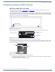
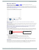
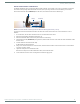


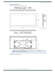
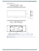
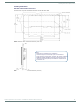
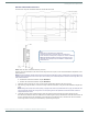
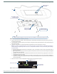
Table Of Contents
- MODERO X® SERIES G5 TOUCH PANELS - INSTALLATION & HARDWARE REFERENCE MANUAL
- Modero X Series G5 Touch Panels
- MXT/D-2001-PAN - 20.3" X Series G5 Panels
- MXT/D-1901-PAN - 19.4" X Series G5 Panels
- MXT/D-1001 - 10.1" X Series G5 Panels
- MXT/D-701 - 7" X Series G5 Panels
- Installing Tabletop (MXT) Panels
- Installing Wall-Mount (MXD) Panels
- A Note About Wall and Rack Installation
- MXD-2001-PAN / MXD-1901-PAN Installation
- MXD-1001 / MXD-701 Installation
- Appendix: Troubleshooting

Installing Tabletop (MXT) Panels
32
Modero X® Series G5 Touch Panels - installation & Hardware Reference Manual
MXT-1001 / MXT-701
Detailed specifications drawings for the MXT-1001 and MXT-701 are available to download from www.amx.com.
Connector Locations - MXT-1001/MXT-701
Two Type A USB ports are located on the rear right corner of the panel (FIG. 17). USB peripherals (i.e. mouse, keyboard) may be
connected to either of the two USB ports on the rear of the device. Updates to the device’s firmware can also made via the USB
ports (see the Modero G5 Configuration and Programming Guide for details). Note that FIG. 17 shows the MXT-1001, but the USB
ports are in a similar location on the MXT-701.
NOTE: Refer to the Power via PoE section on page 32 for details on PoE and Ethernet Cable Installation and Modification.
Power via 13.5V
The MXT-2001-PAN and MXT-1901-PAN use a 13.5V -compliant power supply to provide power to the panel via the 2-pin 3.5mm
captive wire PWR connector. The incoming PWR and GND wires from the power supply must be connected to the corresponding
locations within the PWR connector.
NOTE: Connecting power to the panel should be done using the included 2-pin 3.5mm captive wire connector included with the
device. This connector is retained within its port with locking screws instead of the pins on each side of standard captive wire
connectors, and using force to insert a standard captive wire connector may damage the device.
Wiring a 13.5V Power Connection
To use the 2-pin 3.5mm captive wire connector with a 13.5V -compliant power supply, the incoming PWR and GND wires from
the external source must be connected to their corresponding locations on the connector (FIG. 18). The connector uses locking
screws to insure a connection to the device, so make sure to insert and tighten the screws before applying power.
1. Insert the PWR and GND wires on the terminal end of the 2-pin 3.5mm captive wire cable.
Match the wiring locations of the +/- on both the power supply and the terminal connector.
2. Tighten the clamp to secure the two wires.
Do not tighten the screws excessively; doing so may strip the threads and damage the connector.
3. Verify the connection of the 2-pin 3.5mm captive wire to the external 13.5V -compliant power supply and apply power.
Power via PoE
Power for the MXT-1001 and MXT-701 is supplied via PoE (Power Over Ethernet), utilizing an AMX-certified, capacitive touch-
compliant PoE injector such as the PS-POE-AT High Power PoE Injector (FG423-81) or other approved AMX PoE power source.
The incoming Ethernet cable should be connected to the RJ45 port on the cable attached to the device.
FIG. 17
MXT-1001 - rear view
FIG. 18 NetLinx power connector wiring diagram
USB Ports
Entry for RJ45/PoE Cable
PWR +
GND -
To the Touch Panel
Power Supply