
User's Manual


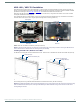
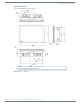
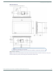
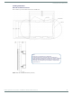
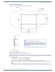
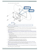
Table Of Contents
- MODERO X® SERIES G5 TOUCH PANELS - INSTALLATION & HARDWARE REFERENCE MANUAL
- Modero X Series G5 Touch Panels
- MXT/D-2001-PAN - 20.3" X Series G5 Panels
- MXT/D-1901-PAN - 19.4" X Series G5 Panels
- MXT/D-1001 - 10.1" X Series G5 Panels
- MXT/D-701 - 7" X Series G5 Panels
- Installing Tabletop (MXT) Panels
- Installing Wall-Mount (MXD) Panels
- A Note About Wall and Rack Installation
- MXD-2001-PAN / MXD-1901-PAN Installation
- MXD-1001 / MXD-701 Installation
- Appendix: Troubleshooting

Installing Wall-Mount (MXD) Panels
47
Modero X® Series G5 Touch Panels - installation & Hardware Reference Manual
MXD-701 Installation Dimensions
FIG. 41 and FIG. 42 provide installation dimensions for the MXD-701:
Use the included Installation Template to ensure proper placement.
NOTE: Using the Installation Template to select the f inal placement of the Backbox is highly recommended. The outside edges of the
template are the same dimensions as the touch panel, which allows you to troubleshoot possible conflicts with wall edges, doors, and
other potential obstacles.
The MXD-1001 uses Installation Template 68-5968-03
The MXD-701 uses Installation Template 68-5968-04
1. Prepare the area by removing any screws or nails from the drywall before beginning the cutout process.
2. After ensuring proper placement, cut out the mounting surface for the Backbox, using the included Installation Template as a
guide.
NOTE: Making sure the actual cutout opening is slightly smaller than the provided dimensions is highly recommended. This
provides a margin for error if the opening needs to be expanded. Too little wall material removed is always better than too much.
FIG. 41
MXD-701-L Installation Dimensions (front view)
FIG. 42 MXD-701 Installation Dimensions (side view)
Notes:
- Dimensions in parenthesis are in millimeters.
- These drawings show a Landscape panel. The dimensions
are the same for Portrait panels, except for the vertical orientation.
Additional detailed installation and product drawings (for both
Landscape and Portrait panels) are available to view/download
at www.amx.com