
User's Manual


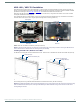
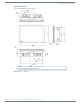
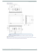
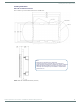
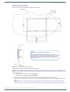
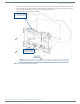
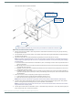
Table Of Contents
- MODERO X® SERIES G5 TOUCH PANELS - INSTALLATION & HARDWARE REFERENCE MANUAL
- Modero X Series G5 Touch Panels
- MXT/D-2001-PAN - 20.3" X Series G5 Panels
- MXT/D-1901-PAN - 19.4" X Series G5 Panels
- MXT/D-1001 - 10.1" X Series G5 Panels
- MXT/D-701 - 7" X Series G5 Panels
- Installing Tabletop (MXT) Panels
- Installing Wall-Mount (MXD) Panels
- A Note About Wall and Rack Installation
- MXD-2001-PAN / MXD-1901-PAN Installation
- MXD-1001 / MXD-701 Installation
- Appendix: Troubleshooting

Installing Wall-Mount (MXD) Panels
48
Modero X® Series G5 Touch Panels - installation & Hardware Reference Manual
3. Thread the incoming Ethernet and USB cables through the surface opening (FIG. 43 and FIG. 44). Note that these figures
show a landscape panel but the installation of a portrait panel is essentially the same, other than the vertical orientation.
Leave enough slack in the wiring to accommodate any re-positioning of the panel.
FIG. 43 shows the MXD-1001 Backbox installation:
FIG. 43
MXD-1001 Backbox Installation (Landscape)
#4 Screws
4X Knock-Outs
Remove for Cable
Routing as Needed
4X Installation Clamp
for Wall Thickness
.31 [12.0] to .98 [.25.0]
Note:
Additional detailed installation and product drawings are available to view/download at www.amx.com