
User's Manual
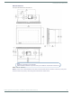
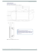
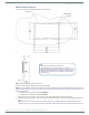
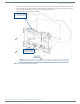
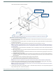
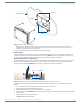
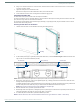
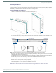
Table Of Contents
- MODERO X® SERIES G5 TOUCH PANELS - INSTALLATION & HARDWARE REFERENCE MANUAL
- Modero X Series G5 Touch Panels
- MXT/D-2001-PAN - 20.3" X Series G5 Panels
- MXT/D-1901-PAN - 19.4" X Series G5 Panels
- MXT/D-1001 - 10.1" X Series G5 Panels
- MXT/D-701 - 7" X Series G5 Panels
- Installing Tabletop (MXT) Panels
- Installing Wall-Mount (MXD) Panels
- A Note About Wall and Rack Installation
- MXD-2001-PAN / MXD-1901-PAN Installation
- MXD-1001 / MXD-701 Installation
- Appendix: Troubleshooting

Installing Wall-Mount (MXD) Panels
51
Modero X® Series G5 Touch Panels - installation & Hardware Reference Manual
6. Using a non-conductive item such as a wooden stick, reinsert the Ethernet cable connector into the device. Ensure that the
connector is properly seated.
7. Tighten the clamp to secure the Ethernet cable.
Make sure the clamp is around the bundled black cable, not the individual wires.
8. Connect the RJ45 connector to its incoming Ethernet cable and apply power.
Uninstalling the MXD-1001
The MXD-1001 is held in place via latch hooks and clips in the Backbox.
In certain circumstances, such as firmware updates or other maintenance that requires accessing the device’s USB or Micro-USB
ports, the device may need to be removed from the Backbox.
The clips that lock down the MXD-1001’s bottom edge (Landscape) or right edge (Portrait) may be unlatched in order to remove
the device from the mounting surface.
Removing the MXD-1001 From Its Backbox
1. The MXD-1001 has three rows of ventilation holes along the molding (FIG. 47):
2. On the bottom (Landscape) or right side (Portrait) of the MXD-1001, locate the seventh and eight ventilation holes from each
edge, on the row closest to the Backbox (FIG. 48):.
3. With a stout, strong point (i.e. push pin or straightened paper clip), carefully press into the access holes in either end of the
molding until the snap is disconnected.
To facilitate the disconnection, grasp the bottom of the panel (Landscape) or right side (Portrait) and pull gently outward until
the side of the panel is free of the snap. Use your other hand to hold stable the front of the touch panel.
NOTE: Always pull on the frame of the touch panel. NEVER pull on the glass edge.
4. When the first side is free, repeat the process with the other.
5. With the edge of the touch panel free, carefully lift up and out (Landscape) or to the left and out (Portrait) to remove the touch
panel from the Backbox. Be careful not to pull on the cables or connectors.
6. To reattach the panel to its Backbox, repeat the installation procedure.
NOTE: For further information, refer to the video available at www.amx.com (go to Newsroom > Videos > Touch Panels).
FIG. 47
MXD-1001 Molding (highlighted in blue)
FIG. 48 Bottom View (Landscape) or Right-Side View (Portrait) of the MXD-1001 showing access holes in molding
Molding Molding
Access holes Access holes
Panel (surface)
#7, #8 #8, #7