Operation/Reference Guide RADIA Eclipse Dimmer Modules RE-DM4 (120V, 240V) RE-DM6 (120V, 240V) R AD I A L i g h t i n g S ol u t i ons Last Updated: 6/15/2007
AMX Limited Warranty and Disclaimer All products returned to AMX require a Return Material Authorization (RMA) number. The RMA number is obtained from the AMX RMA Department. The RMA number must be clearly marked on the outside of each box. The RMA is valid for a 30-day period. After the 30-day period the RMA will be cancelled. Any shipments received not consistent with the RMA, or after the RMA is cancelled, will be refused. AMX is not responsible for products returned without a valid RMA number.
Table of Contents Table of Contents Radia Eclipse RE-DM4 Dimmer Module ..............................................................1 Overview .................................................................................................................. 1 Specifications............................................................................................................ 2 Suggested Loads ......................................................................................................
Table of Contents Connecting high-voltage input power and loads........................................................... 21 RDA-ENC6B 120/208 VAC line input (three phase)....................................................... 21 RDA-ENC6B three phase line input connector reference .............................................. 22 RDC-PFC power distribution and line input references ................................................. 23 Installing RDM Modules into an Enclosure ..............................
Table of Contents Economical Dimming Curve (2) ..................................................................................... 50 0-10VDC Curve (3) ........................................................................................................ 51 0-12VDC Curve (4) ........................................................................................................ 53 Lutron FDB Curve (5).....................................................................................................
Table of Contents Set Default Ramp Time.................................................................................................. 85 Ramp To Level............................................................................................................... 86 Undefine Dimmer .......................................................................................................... 86 Phase Query ........................................................................................................
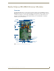
Radia Eclipse RE-DM4 Dimmer Module Radia Eclipse RE-DM4 Dimmer Module Overview The RE-DM4 RADIA Eclipse 4-Channel Integrated Dimmer Module (120 VAC: FG706-01; 240 VAC: FG706-02) controls up to six circuits with four 1200-watt onboard dimmers and two satellite connectors for RDM series dimmer or switch modules. The RE-DM4 is designed for use with the RDA series of enclosures in an AMX Lighting™ modular digital dimming system. The RE-DM4 is controlled by AXLink or by dry (contact) closures.
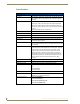
Radia Eclipse RE-DM4 Dimmer Module Specifications RE-DM4 Specifications Dimensions (HW) 5.75" x 10.0" (146.50 mm x 254.00 mm) Line Input • 120, 240 VAC, single phase, 2W+G, 50/60 Hz, 2400 W, one feed • 120, 120/240, 240 VAC, single phase, 3W+G, 50/60 Hz, 4800 W, dual feed Output • 1200 W max. per channel @120, 240 VAC • 2400 W max. total, all four channels on with single 2400 W feed • 4800 W max.
Radia Eclipse RE-DM4 Dimmer Module Suggested Loads Dimmed Switched Incandescent Motors Neon, cold-cathode Fans Caution: Pre-Installation Notes This unit should be installed only by qualified electrical personnel, and in compliance with all national electrical codes, local codes and ordinances.To prevent possible personal injury or death, disconnect power to the enclosure at the breaker box before attempting to work with any AMX Lighting modules.
Radia Eclipse RE-DM4 Dimmer Module Line-In Connections Using two feeds for Line 1 and Line 2 provides two 2400 W inputs. With a jumper, Line 1 and Line 2 provides a single 2400 W input. Dual 2400 W Inputs without jumper Single 2400 W Input with jumper FIG. 3 Line-In Connections for the RE-DM4 Lighting Application Drawings The RE-DM4 has two preferred lighting application methods, as shown in FIG. 4 and FIG. 5 Example A Single input 120 or 240 VAC 1Ø Single-phase, four load FIG.
Radia Eclipse RE-DM4 Dimmer Module Example B Dual Input 120, 120/240, or 240 VAC 1Ø Single-phase, four load FIG. 5 Lighting Application for the RE-DM4, Example B Please refer to the AMX Lighting Programming section on page 37 for more information.
Radia Eclipse RE-DM6 Dimmer Module Radia Eclipse RE-DM6 Dimmer Module Overview The RE-DM6 6-Channel Integrated Dimmer Module (120V: FG706-03; 240V: FG706-04) controls up to six circuits with six 1200-watt onboard dimmers (FIG. 6). The RE-DM6 is designed for use with the RDA series of enclosures, in an AMX Lighting™ modular digital dimming system. The RE-DM6 is controlled by AXLink or by dry (contact) closures.
Radia Eclipse RE-DM6 Dimmer Module Specifications RE-DM6 Specifications Dimensions (HW) 5.75" x 10.0" (146.05 mm x 254.00 mm) Weight 4.5 lbs (2.04 kg) Line input • 120, 240 VAC, single phase, 2W+G, 50/60 Hz, 2400 W, one feed • 120, 120/240, 240 VAC, single phase, 3W+G, 50/60 Hz, 4800 W, dual feed Output • 1200 W max. per channel @120, 240 VAC • 2400 W max. total, all 6 channels on with single 2400 W feed • 4800 W max.
Radia Eclipse RE-DM6 Dimmer Module Suggested Installation Loads Dimmed Switched Incandescent Motors Neon, cold-cathode Fans Caution: Pre-Installation Notes This unit should be installed only by qualified electrical personnel, and in compliance with all national electrical codes, local codes and ordinances. To prevent possible personal injury or death, disconnect power to the enclosure at the breaker box before attempting to work with any AMX Lighting modules.
Radia Eclipse RE-DM6 Dimmer Module Lighting Application Drawings The RE-DM6 has two preferred lighting application methods, as shown in FIG. 8 and FIG. 9. Example A Single Input 120 or 240 VAC 1Ø Single-phase, six load FIG. 8 Lighting Application for the RE-DM6, Method A Example B Dual Input 120, 120/240 VAC Single-phase, six load FIG. 9 Lighting Application for the RE-DM6, Method B Please refer to the AMX Lighting Programming section on page 37 for more information.
Radia Eclipse RE-DM6 Dimmer Module 10 RE-DM4 and RE-DM6 RADIA Eclipse Dimmer Modules
AMX Lighting Systems AMX Lighting Systems Overview The AMX Radia Lighting Control SystemTM employs a dual-platform programming architecture that supports the NetLinx programming language. The AMX Lighting product line is modular by design, and includes a wide variety of integrated dimmer control modules, dimmer modules, and switch/relay modules.
AMX Lighting Systems AMX Lighting Control Equipment The following table lists all of the AMX Lighting Control System equipment currently available. Refer to the installation sheets for these enclosures, control modules, and dimmer modules for detailed wiring drawings, application notes, and specifications.
AMX Lighting Systems AMX Lighting Control Equipment (Cont.
AMX Lighting Systems 14 RE-DM4 and RE-DM6 RADIA Eclipse Dimmer Modules
Installation Installation Space Requirements AMX Lighting control installations require very little space. Space for enclosures is the main concern. All enclosures are mounted flush on a vertical surface, and must have a minimum clearance of 12" (304.8 mm) above and below to allow for air circulation. Physical dimensions for each enclosure are described in the Enclosure Dimensions section on page 17.
Installation connection, the 12VDC supply to the processor will allow program changes if the 120VAC supply is cut off. Conduit Conduit runs depend on the enclosures you use and their AMX Lighting modules. All enclosures have conduit knockouts on the top for high-voltage connections, and knockouts on the bottom for low-voltage connections. All conduit knockouts allow for 1/2, 3/4, and 1-inch (12.7 mm, 19.0 mm, and 25.4 mm) conduits as shown in FIG. 11.
Installation Enclosure Dimensions RDA-ENC2, -ENC4, and -ENC6 enclosure and dimensions FIG. 12 shows the dimensions for the RDA-ENC2, RDA-ENC4, and RDA-ENC6 enclosures. RDA-ENC2 RDA-ENC4 0.75" (19.05 mm) RDA-ENC6 6.0" (152.4 mm) Top View Side View (for all enclosures) Internal View 12.0" (304.8 mm) Bottom View 6.0" (152.4 mm) 12.0" (304.8 mm) 18.0" (457.2 mm) FIG. 12 RDA-ENC2, RDA-ENC4, and RDA-ENC6 enclosure dimensions RDA-ENC6B and RDA-ENC12B enclosures and dimensions FIG.
Installation Mounting AMX Lighting Enclosures AMX Lighting enclosures must be mounted on a vertical surface with a minimum of 12" (304.8 mm) clearance above and below the enclosure. FIG. 14 shows the centerline reference points and dimensions. The clearance above and below the enclosure is necessary for proper ventilation and heat dissipation. 1. Remove the front cover by removing the screws at the bottom of the enclosure; two tabs suspend the cover from the top. 2.
Installation All high-voltage connections must comply with Class 1 wiring codes. Connecting high-voltage, single-phase input power and loads Follow these steps to wire high-voltage (120 VAC and 240 VAC), single-phase power connections (FIG. 16) to any of the AMX Lighting modules. Ground (green) Hot (black) Ground (green) Neutral (white) Hot (black) Neutral (white) to Enclosure ground terminal FIG.
Installation RDA-ENC6B 120 VAC single phase line input FIG. 17 shows a 120 VAC single-phase (2 W + G) wiring diagram for the RDA-ENC6B line input terminal block. 1 2a 2b 3 FIG. 17 RDA-ENC6B 120 VAC single-phase (2 W + G) wiring diagram RDA-ENC6B 120/240 VAC line input (single phase) FIG. 18 shows a 120/240 VAC single-phase (3 W + G) wiring diagram for the RDA-ENC6B line input terminal block. 1 2a 2b 3 FIG.
Installation Connecting high-voltage input power and loads Follow these steps to wire high-voltage (120 VAC and 240 VAC) power connections (FIG. 19) to any of the AMX Lighting modules Connect to neutral block RDA-ENC6B line input terminal 1 2a 2b 3 These connections are factorywired FIG. 19 High-voltage, three-phase input power 1. Connect the green ground wire(s) to the copper ground lug on the enclosure. Ensure the ground wire is properly connected to earth ground. 2.
Installation While it is possible to wire the enclosure with 3-phase Y, please remember a single RE-DM4 or RE-DM6 will only support one Y-phase. RDA-ENC6B three phase line input connector reference FIG. 21 shows a sample RDA-ENC6 three phase (4 W + G) line input connector and dimmer references. 1 2a 2b 3 Line input 1 feeds dimmers 1 and 4 Line input 2a feeds dimmer 5 Line input 2b feeds dimmer 2 Line input 3 feeds dimmers 3 and 6 FIG.
Installation RDC-PFC power distribution and line input references FIG. 22 shows the power distribution and line input references for the RDC-PFC line inputs. RDC-PFC Line input 1 feeds dimmers 1 and 4 Line input 2a feeds dimmer 5 Line input 2b feeds dimmer 2 Line input 3 feeds dimmers 3 and 6 FIG. 22 RDC-PFC power distribution and line input reference references While it is possible to wire the enclosure with 3-phase Y, please remember a single RE-DM4 or RE-DM6 will only support one Y-phase.
Installation Installing RDM Modules into an Enclosure Installing any of the RDM modules is an easy task. The individual modules are shipped with the four mounting screws enclosed. To prevent possible personal injury or death, disconnect power to the enclosure at the breaker box before attempting to install any AMX Lighting modules. FIG. 23 illustrates the inside of an RDA-ENC6 enclosure and the mounting slots. The modules are positioned in the appropriate slot and secured using the supplied screws.
Installation Low-Voltage Connections All low-voltage connections must comply with Class 2 wiring codes. The low-voltage area in the AMX Lighting controllers contain connections and DIP switches for AXLink, dry closures, and module jack connectors. On the controller cards, low-voltage power for the board is supplied either by line power, optional auxiliary power supply (RDA-PSM), or the +12 VDC pin on the AXLink connector.
Installation Green status LED indicator When you apply power to the AMX Lighting Control System, the green status LED notes its conditions: It is on full when AC power is applied to the control module, and no Axlink communication is present. It blinks on and off when AC power is applied to the control module, and Axlink communication is present. It blinks on and off rapidly when no AC power is applied to the control module, and the board is powered via Axlink or Aux In DC power.
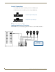
Installation FIG. 26 shows an example of how to interconnect two AMX Lighting RE-DM4 controllers and a AXLink wall panel. Neutral HOT (1) Neutral HOT (2) RE-DM4 (pack 1) RE-DM4 (pack 1) AXLink connector AXLink connector (black) (black) AXLink FIG. 26 AXLink configuration sample Configuring and connecting AXLink On all AMX Lighting controllers, DIP switch SW1 sets the AXLink device number. The device number is determined by the value of all the switch position settings.
Installation Turning off all switches invokes "Installer Test Mode": all lighting circuits at 100%. 1. Power off the enclosure unit at the breaker panel. 2. Locate the SW1 DIP switch (AXLink ADDRESS) on the controller circuit card and set the device number, using the values shown in the proceeding table. 3. Connect the four-pin AXLink male connector into the four-pin female AXLink connector on the controller circuit card. FIG. 27 shows how to wire the AXLink connector to a Central Controller system.
Installation Dry Closures The RE-DM4 and RE-DM6 have two dry closure inputs via a 4-pin mini-phoenix connector. The inputs are an open collector pulled up to 5 VDC. The status is normally open, channel Off, with the closure released. When an input is pulled low to ground and falls below 3 VDC, the AMX Lighting system sees the action as an input closure, the AXLink channel is turned On, and a push sent to the Axcess Central Controller.
Installation Default Presets Preset Number Description 1 Channel 1, Channel 1 @ 100% in 1 second 2 Channel 2, Channel 2 @ 100% in 1 second 3 Channel 3, Channel 3 @ 100% in 1 second 4 Channel 4, Channel 4 @ 100% in 1 second 5 Channel 5, Channel 5 @ 100% in 1 second 6 Channel 6, Channel 6 @ 100% in 1 second 7 Channels 1-6 @ 100% in 1 second 8 Channels 1-6 @ 0% in 1 second 126 Emergency Dry Closure On Channel 1-6 @ 100% in 1 second 127 Failsafe Dry Closure Off Channels 1-6 @ 0% in 1 secon
Radia Lighting System Configuration Pages Radia Lighting System Configuration Pages Overview The AMX Radia Web pages provide a simple interface from which an installer/user may perform lighting system configuration and setup tasks without needing access to an AMX touch panel. The web pages reside on the AMX master and may be accessed through a compatible Web browser. The AMX Radia configuration web pages were designed with setup functionality in mind and not everyday control.
Radia Lighting System Configuration Pages The AMX master must be running firmware v3.21.343 or higher for the Radia Eclipse configuration pages to work as expected. Main Lighting System Page Clicking on the AMX Radia RE-DM4,Radia RE-DM6 - 41001:1:0 link opens the Radia Configuration Manager page (FIG. 30). FIG. 30 Radia Configuration Manager This page displays basic system status information and options for navigating to and configuring a particular component.
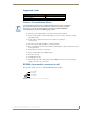
Radia Lighting System Configuration Pages Device Configuration Page This page provides the ability to name your specific Radia device by typing an installation-specific label in the Lighting Area Name field (FIG. 31). FIG. 31 Device Configuration Page To configure a particular device from the Device Configuration page: 1. In the main Radia Configuration Manager page, click the Configure button. 2. In the Lighting Area Name field, enter a descriptive name for the area.
Radia Lighting System Configuration Pages 6. Click the Accept button at the bottom of the page (FIG. 32) to save your changes. FIG. 32 Accept button You do not need to click the Accept button to save changes if you only adjusted the dimmer levels by using the Level slidebar. To exit a Radia configuration page, you must choose Cancel, whether you have chosen to accept the changes or not. Each Radia device has, by default, 11 predefined presets, also shown on the Device Configuration page (FIG.
Radia Lighting System Configuration Pages To modify an existing preset: 1. In the Device Configuration page, scroll down to the preset to be modified. 2. For more information on the preset, click the Info button for the preset. This opens a new information box with the preset’s dimmer and level information. When finished, close the box. 3. In the Label field, change the preset’s label if necessary. 4.
Radia Lighting System Configuration Pages To create a new preset: 1. Scroll to the bottom of the Device Configuration page and click the Add Preset button (FIG. 35). FIG. 35 New Preset button 2. Enter a name for the new preset in the Label field. 3. Enter a time (0-255) in the Preset Time field. If you do not add a time, a default value of "1" will be entered. 4. Click the Configure button to open the New Preset Configuration page (FIG. 34). 5.
AMX Lighting Programming AMX Lighting Programming Introduction This section provides an overview of AMX Radia Eclipse concepts and programming. For detailed protocol information, please see the Appendix B: Radia Lighting Programming section on page 76. This section explains firmware, channels, programming commands, and lighting curves.
AMX Lighting Programming Presets: Defined vs. Undefined Levels Understanding the meaning of the terms "defined" and "undefined", as used in the context of levels in a Radia lighting system, is necessary for properly setting up presets for multiple lighting zones. Each dimmer on the Radia has a TRUE/FALSE status associated with it that is referred to as "defined". The state of the defined status is used when saving presets so that the Radia knows which dimmers are to be affected when the preset is recalled.
AMX Lighting Programming Also, the configuration of the Radia is such that dimmers 1-3 are controlling lights in room A (a conference room) and dimmers 4-6 are controlling lights in room B (another conference room). In each of these room is a 3-button wall-mounted control panel that provides control of the local lights: Meeting Mode Meeting Mode Presentation Mode Presentation Mode Off Off FIG.
AMX Lighting Programming Lighting Systems Overview AMX Lighting systems are based on a modular construction. The modular structure has three basic components: Controller, Enclosure, and Dimmer/Switch Modules. All AMX Lighting controllers have six channels of control. Seven channels of control will always require the use of two controllers. In order to have the controllers address different dimmers’ ranges, each pack/group of six channels have a specific range. The packs may be controlled by Cafe Duet code.
AMX Lighting Programming Control Curves and Low End Settings The market currently has a great selection of new lamp and ballast options. Each one has properties and dimming characteristics that present a new challenge for the dimmer manufacturer to provide an appropriate dimmer. What was designed as a standard incandescent dimmer must now be able to control electronic ballast, incandescent lamps, low voltage track lighting, and a host of new transformers.
AMX Lighting Programming 42 RE-DM4 and RE-DM6 RADIA Eclipse Dimmer Modules
Appendix A: AMX Lighting Curves Appendix A: AMX Lighting Curves Overview Thousands of different lighting fixtures with unique shapes and styles exist, all designed to do something visibly different with light. Any one of those fixtures in a hundred different locations could produce a different lighting effect. Two identical lights in different locations could produce different reflections and shadows.
Appendix A: AMX Lighting Curves The Radia Eclipse controllers can employ a low-end cut-off that allows the dimmer to turn on to a specified level or to dim down to no less than a specified level. This level at which the dimmer turns on is called the Low End Setting. This is also used to turn a light off at the low end point when dimming down from a bright level. A low end setting of 25 applied to the standard dimming curve would prevent the fixture from being dimmed below Level 25.
Appendix A: AMX Lighting Curves This third characteristic controls the RLY output of the RDM connections on the RE-DM4. Previous versions of Radia would turn on the RLY outputs at INPUT (from control system) levels of 1 or above. Radia Eclipse turns on the RLY output at the OUTPUT level of 1, so that it can effected by curve choices and low end settings. These three characteristics are applied to different AMX Lighting dimmers to change the way the dimmers perform.
Appendix A: AMX Lighting Curves Curve Configuration Each Radia dimmer maintains non-volatile configuration information that is necessary to the operation of the dimmer such as presets, curves, ramp times, etc. The configuration can be uploaded and downloaded from the dimmer for the purposes of providing a user interface to ease the configuration process and for archival purposes. Curves Curves are used to define the relationship between the dimmer's level and the actual output voltage.
Appendix A: AMX Lighting Curves The following table provides a general relationship between load type and which curve to use: Load Type Curves Incandescent Curve 1 – Standard dimming curve Curve 2 – Energy efficient, uses 10% less energy. Advance Mark VII Ballast Curves 3, 5, or 6 4-wire Ballasts Curve 5 – Used for some ballasts Curve 7 – Used with other ballasts with the RDM-DC series of modules. Low voltage Curves 5, 6, B, C – All logarithmic curves with slight variations in the curve.
Appendix A: AMX Lighting Curves FIG. 41 shows the dimmer turning on to level 20 from an off condition. It maintains the level until the dimmer reaches a level above 20%, at which point the dimmer output starts to climb again. Conversely, it will dim down to 20% and maintain that level until it turns off. Relay turn on level = 1% Dimming Range = 56 - 120 VAC. FIG. 41 Curve 1 Voltage Output in 240V AC FIG. 42 shows the low-voltage output of the RDM-HDC module.
Appendix A: AMX Lighting Curves FIG. 43 shows three different Low End Settings of 5%, 10%, and 20%. Each curve holds its assigned value until the dimmer level reaches 0. Ramping up from level 0 will turn on the lamps at three different levels respectively. Low End settings can be used to correct for problems in dimming various lighting products at low levels. Dimming ranges can be controlled using the low end setting.
Appendix A: AMX Lighting Curves Economical Dimming Curve (2) Similar to Curve 1, Curve 2 rolls off at 90% of the top end or about 105 volts maximum. FIG. 44 shows a curve that reduces the maximum output to 90% of maximum to conserve energy. It is also called the 'energy saving curve'. Relay turn on level = 1% Dimming Range = 0 - 114 VAC. FIG. 44 Curve 2 at 120V AC FIG. 45 Curve 2 at 240 VAC FIG. 46 shows the low-voltage output of the RDM-HDC module.
Appendix A: AMX Lighting Curves 0-10VDC Curve (3) FIG. 47 shows the output voltage of a dimmer. It has a smooth taper and a cut off point of 25 volts. This curve will shrink incandescent dimming range 25%. Relay turn on level = 1% Dimming Range = 30 - 115 VAC. FIG. 47 Curve 3 voltage output in volts RMS FIG. 48 Curve 3 at 120 VAC FIG. 49 Curve 3 at 240 VAC FIG. 50 shows the output voltage of the RDM-HDC module. The voltage range is from 2.6 to 9.3 VDC when attached to test ballast.
Appendix A: AMX Lighting Curves FIG.
Appendix A: AMX Lighting Curves 0-12VDC Curve (4) FIG. 51 shows the output voltage of a dimmer. There is a noticeable gap at the low end. Curve 4 is a smooth fade until 15%, then it rolls off sharply. Relay turn on level = 1% Dimming Range = 0 - 120 VAC. FIG. 51 Curve 4 Voltage output in Volts RMS FIG. 52 Curve 4 at 120 VAC FIG. 53 Curve 4 at 240 VAC FIG. 54 shows the output voltage of the RDM-HDC module. Curve 4 is primarily used for control of Prescolite Intelect Ballast, using the RDM-HDC module.
Appendix A: AMX Lighting Curves FIG. 54 Curve 4 Voltage output in volts DC Lutron FDB Curve (5) FIG. 55 shows the output voltage of a dimmer. It quickly dims the high end and extends the mid-range dimming control with a cut-off at 18 volts. This curve can be useful with two wire dimmable fluorescent ballasts. Relay turn on level = 1% Dimming Range = 16 - 120 VAC. FIG. 55 Curve 5 Voltage output in Volts RMS FIG.
Appendix A: AMX Lighting Curves FIG. 57 Curve 5 at 240 VAC FIG. 58 shows the output voltage of Curve 5 applied to the RDM-HDC module. It turns on to about 2 volts and rises to 12 VDC. There is a large increase in output above 98%. FIG.
Appendix A: AMX Lighting Curves Advance Mark VII Curve (6) FIG. 59 shows the voltage output of Curve 6 applied to a dimmer. Curve 6 will smoothly dim the high end and extend the low-end range of dimming. This curve can be useful for dimming applications using transformers and requiring a more precise low end dimming range. Relay turn on level = 1% Dimming Range = 21 - 120 VAC. FIG. 59 Curve 6 Voltage output in Volts RMS FIG. 60 Curve 6 at 120 VAC FIG. 61 Curve 6 at 240 VAC FIG.
Appendix A: AMX Lighting Curves FIG.
Appendix A: AMX Lighting Curves 12% Roll Off (7) FIG. 63 Curve 7 at 120 VAC FIG. 64 Curve 7 at 240 VAC FIG. 65 shows the output voltage of a dimmer. This curve follows the Standard dimming curve (Curve 1) for the first half of its control. After Level 50, the curve rolls off to 40 volts before cut off. This provides a 30% reduction in dimming. Relay turn on level = 1% Dimming Range = 39 - 1 20 VAC. FIG.
Appendix A: AMX Lighting Curves FIG. 66 shows the DC output voltage of Curve 7 applied to the RDM-HDC module. It starts at 3 VDC and rises to 12 VDC. FIG.
Appendix A: AMX Lighting Curves 19% Roll Off (8) FIG. 67 Curve 8 at 120 VAC FIG. 68 Curve 8 at 240 VAC FIG. 69 shows the output voltage of a dimmer. This curve follows the Standard dimming curve (Curve 1) for the first 50% and then levels off to a 50 volts cut-off. This can be used on Advance Mark X ballasts. Relay turn on level = 1% Dimming Range = 52 - 120 VAC. FIG.
Appendix A: AMX Lighting Curves FIG. 70 shows the output voltage of the RDM-HDC module. The low end starts at 4 volts and slowly rises to 12 VDC. This curve provides precise mid-range dimming. FIG.
Appendix A: AMX Lighting Curves 33% Roll Off (9) FIG. 71 Curve 9 at 120 VAC FIG. 72 Curve 9 at 240 VAC FIG. 73 shows the output voltage of a dimmer. Curve 9 starts at 70 volts and rises to 120 volts for a dimming range of 40%. This curve can be used to dim some fan motors. Use this curve when very little voltage range can be tolerated. Relay turn on level = 1% Dimming Range = 72 - 120 VAC. FIG.
Appendix A: AMX Lighting Curves FIG. 74 shows the output voltage of the RDM-HDC module. Curve 9 starts at 5 volts and rises to 12 VDC. This provides a dimming range of 7 VDC. FIG.
Appendix A: AMX Lighting Curves S-Curve #1 (A) FIG. 75 Curve A at 120 VAC FIG. 76 Curve A at 240 VAC FIG. 77 shows the output voltage of a dimmer. Curve A is an alternate version of the Standard dimming curve (Curve 1). It rolls off the high end quickly and extends the dimming range in the middle with a sharper roll off starting at 20% dimming level. Relay turn on level = 1% Dimming Range = 0 - 120 VAC. FIG.
Appendix A: AMX Lighting Curves FIG. 78 shows the output voltage of the RDM-HDC module. Curve A starts at 2 volts and slowly rises. It increases 3 volts in the last 10% of its travel. This curve can be used with 0-12 VDC dimming ballasts like Prescolite Intelect ballasts. FIG.
Appendix A: AMX Lighting Curves Log-Curve #1 (B) FIG. 79 Curve B at 120 VAC FIG. 80 Curve B at 240 VAC FIG. 81 shows the output voltage of a dimmer. It rolls off the high end slower and becomes somewhat linear until a roll-off at 18 VAC. Relay turn on level = 1% Dimming Range = 18 - 115 VAC. FIG. 81 Curve B Voltage output in Volts RMS FIG. 82 shows the output voltage of Curve B applied to the RDM-HDC module. The turn on voltage is 2VDC and rises to 10VDC.
Appendix A: AMX Lighting Curves FIG. 82 Curve B Voltage output in Volts DC Log-Curve #2 (C) FIG. 83 Curve C at 120 VAC FIG.
Appendix A: AMX Lighting Curves FIG. 85 shows the output voltage of a dimmer. This curve starts at the low end at about 20 volts and gently rises to only 113 volts. This curve reduces dimming range by about 20%. Relay turn on level = 1% Dimming Range = 20 - 115 VAC. FIG. 85 Curve C Voltage output in Volts RMS FIG. 86 shows the DC output voltage of Curve C applied to the RDM-HDC module. It starts at 2VDC and rises to 10VDC. This curve can be used with 0-10 VDC dimming ballasts. FIG.
Appendix A: AMX Lighting Curves FIG. 88 Curve D at 240 VAC FIG. 89 shows the output voltage of a dimmer. Curve D is an alternate version of Curve A. It rolls off the high end slower and extends the dimming range in the middle with a sharp roll off starting at 25% dimming level. Relay turn on level = 1% Dimming Range = 0 - 115 VAC FIG. 89 Curve D Voltage output in Volts RMS FIG. 90 shows the output voltage of the RDM-HDC module. Curve D is a variation of Curve A but at a 10% reduction.
Appendix A: AMX Lighting Curves 10% Off Curve (N) FIG. 91 Curve N at 120 VAC FIG. 92 Curve N at 240 VAC FIG. 93 shows the output voltage of the RDM-HDC module. This is an incandescent dimmer always on, starting at Level 9. Relay turn on level = 09. The RDM-HDC module will output 12 VDC above Level 09. FIG.
Appendix A: AMX Lighting Curves Always OFF Curve (O) FIG. 94 Curve O at 120 VAC FIG. 95 Curve O at 240 VAC FIG. 96 is an incandescent dimmer, always off. No Level command will turn this dimmer on. Relay turn on level = none. The RDM-HDC module will output no voltage. FIG.
Appendix A: AMX Lighting Curves Always ON Curve (F) FIG. 97 Curve F at 120 VAC FIG. 98 Curve F at 240 VAC FIG. 99 is an incandescent dimmer, always on. No command will turn this dimmer off. Relay turn on level = always on. The RDM-HDC module will output a constant 12 VDC. FIG. 99 Curve F Voltage output in Volts RMS FIG. 100 is the voltage plot of the original Radia MC Series in FDB mode.
Appendix A: AMX Lighting Curves FIG. 100 Curve M & S Voltage output in Volts RMS FIG. 101 Curve R at 120 VAC FIG.
Appendix A: AMX Lighting Curves FIG. 103 Curves 5 & B at 120 VAC FIG. 104 Curves 5 & B on the Radia Eclipse RE-DM6 at 120 VAC FIG. 105 Curves 6 & C at 120 VAC FIG.
Appendix A: AMX Lighting Curves FIG. 107 Curves A & D at 120 VAC FIG.
Appendix B: Radia Lighting Programming Appendix B: Radia Lighting Programming Levels The Radia only supports 8-bit levels with values from 0-255; equivalent to 0-100%. Each AXLink level (1-6) corresponds o a dimmer (1-6). The levels can be used both as feedback and control. As feedback, when a dimmer is ramping (i.e. changing level), the Radia will send notification to the master as the level changes EXCEPT as noted below.
Appendix B: Radia Lighting Programming Channels The channels are defined as follows: Channels Channel(s) Function Description 1-128 Status of Presets Feedback only. Reflects the currently active presets. 129 Ramp dimmer 1 up Ramps dimmer up at the default ramp time rate while channel is on. Will be turned off by Radia when dimmer reaches 100%. Defines this dimmer for the purposes of presets. 130 Ramp dimmer 2 up Ramps dimmer up at the default ramp time rate while channel is on.
Appendix B: Radia Lighting Programming Channels (Cont.) Channel(s) Function Description 144 Ramp all dimmers to 0% Ramps all dimmers to 0% at the default ramp time rate. Will be turned on at any time when all dimmers are at 0%, will be turned off (if on) otherwise. Defines all dimmers for the purposes of presets. 145 Ramp active preset up Ramps all dimmers up that are defined in the last recalled preset at the default ramp time rate. Will be turned off when all preset associated dimmers reach 100%.
Appendix B: Radia Lighting Programming In contrast with previous versions of Radia dimmers, Radia Eclipse dimmers accept both upper- and lower-case strings All string responses are preceded with a single byte 12 ($0C in HEX or ASCII character '?') and followed by a carriage return (13 or hex $0D), line feed (10 or hex $0A), and a question mark '?' (63 or hex $3F).
Appendix B: Radia Lighting Programming Ramp Dimmers Down This function ramps down the specified dimmer(s) until the ramping stops or the dimmer(s) reach 0%. Note that this function uses the terminating carriage return (ASCII 13) to stop ramping, so do not send the carriage return with the string. The ramp rate for this function is the default ramp time as established by the 'RT' command.
Appendix B: Radia Lighting Programming Ramp active preset up This function ramps up the currently active (last recalled) preset until the ramp is stopped or all dimmers in the preset reach 100%. Note this function uses the terminating carriage return (ASCII 13) to stop ramping, therefore the carriage return must not be sent with the string. The ramp rate for this function is the default ramp time as established by the 'RT' command.
Appendix B: Radia Lighting Programming Recall Preset This function recalls the specified preset over an optionally specified time. If time is not specified, then the rate used when saving the preset used.
Appendix B: Radia Lighting Programming Set curve This function sets the specified dimmer(s) to follow the specified curve. See the Curves section on page 46 for a description of the curves.
Appendix B: Radia Lighting Programming Low End Status This function returns the low end settings assigned to each dimmer. Low End Status String: []LE? Response: P:,,,,, Example: SEND_STRING Radia,"'LE?',13" Request current low end settings Response: "12,'P01:000,005,000,000,005,000',13,10,'?'" If is specified, it must be 1. Dimmer Status This function returns the status of the specified dimmer.
Appendix B: Radia Lighting Programming Set Default Level Time This function sets the time taken for a level to change from its current level to a new level when using a level command.
Appendix B: Radia Lighting Programming Ramp To Level This function ramps the specified dimmer(s) to the specified level over the optionally specifiable time. Ramp To Level String: L[T
Appendix B: Radia Lighting Programming Phase Query This function queries the current state of the phase detection system. Phase zero-crossing detection occurs at all times. In the presence of a phase/zero-cross error, the AXLink LED will blink very fast (>10Hz) and all string responses (where existent) will be "PHASE ERROR!!".
Appendix B: Radia Lighting Programming SEND_COMMANDs The Radia Eclipse firmware supports the SEND_COMMANDs listed in the table below. The number of SEND_COMMANDs is expected to grow as we transition away from using the SEND_STRING method of controlling Radia dimmers. Note that most SEND_COMMANDs do not have responses. With those that do, they respond with a COMMAND, not a string.
Appendix B: Radia Lighting Programming Ramp Preset Down (NEW) This function ramps down the specified or currently active (last recalled) preset until the ramp is stopped or the all dimmers in the preset reach 0%. If is not specified, then the last recalled preset is ramped. Note this function uses the 'PS' command to stop ramping. The ramp rate for this function is the default ramp time as established by the 'RT' command.
Appendix B: Radia Lighting Programming Set Curve This function sets the specified dimmer(s) to follow the specified curve. See the Curves section on page 46 for a description of the curves. Set Curve Command: SCC Response: None Examples: SEND_COMMAND Radia,'SC1C1' Set dimmer 1 to curve 1 SEND_COMMAND Radia,'SC1-4CN' Set dimmers 1-4 to curve N SEND_COMMAND Radia,"SCAC3' Set all dimmers to curve 3 Curve Status (NEW) This function returns the curves assigned to each dimmer.
Appendix B: Radia Lighting Programming Reboot (NEW) This function reboots the dimmer and initializes it to its power-up state. The device will go off-line and then return on-line with the master controller. Reboot Command: RESET Response: None Example: SEND_COMMAND Radia,'RESET' Reboot dimmer Set Default Level Time This function sets the time taken for a level to change from its current level to a new level when using a level command.
Appendix B: Radia Lighting Programming Ramp to Level This function ramps the specified dimmer(s) to the specified level over the optionally specifiable time. Ramp To Level Command: PL[T
Appendix C: Troubleshooting Appendix C: Troubleshooting Software Issues The following items address software-related technical support issues. The following steps describe the steps necessary to use NetLinx software in Terminal Emulator mode. Using PASS mode Use the PASS mode with a computer running capable of connecting to a NetLinx master controller, and the AMX Lighting controller connected as an AXLink device.
Appendix C: Troubleshooting Testing AMX Lighting features In general, any SEND_STRING valid for the Radia can be used in PASS mode. The ones below are a useful subset.
Appendix C: Troubleshooting Hardware Issues The following items address hardware related technical support issues. You should make sure that each AXLink device number is a unique number. Duplicate AXLink device numbers will cause problems. The same holds true for SEND_STRING pack numbers, so do not duplicate pack numbers as well. Troubleshooting hardware The following table shows the different areas that should be checked if a hardware problem arises.
Appendix C: Troubleshooting 96 RE-DM4 and RE-DM6 RADIA Eclipse Dimmer Modules
Appendix C: Troubleshooting RE-DM4 and RE-DM6 RADIA Eclipse Dimmer Modules 97
AMX. All rights reserved. AMX and the AMX logo are registered trademarks of AMX. AMX reserves the right to alter specifications without notice at any time. ©2007 6/07 It’s Your World - Take Control™ 3000 RESEARCH DRIVE, RICHARDSON, TX 75082 USA • 800.222.0193 • 469.624.8000 • 469-624-7153 fax • 800.932.6993 technical support • www.amx.