
User manual


AMX Lighting Programming
41
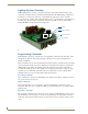
RE-DM4 and RE-DM6 RADIA Eclipse Dimmer Modules
Control Curves and Low End Settings
The market currently has a great selection of new lamp and ballast options. Each one has properties and
dimming characteristics that present a new challenge for the dimmer manufacturer to provide an
appropriate dimmer. What was designed as a standard incandescent dimmer must now be able to control
electronic ballast, incandescent lamps, low voltage track lighting, and a host of new transformers. One
way to solve many of these problems is to apply different control curves to each dimmer and to provide a
variable low-end cut-off point.
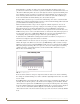
A dimming curve is a graphical or electronic representation of the amount of control that must be applied
to a dimmer in relation to the dimmer output. This is much like a directional map that the controller
follows. The amount of control is typically measured in percent; from an Off-state of level 0 to an On-
state at level 100. Dimmer output is measured in volts. A graphical representation of a dimming curve is
usually the percentage of dimming in relation to the output voltage (RMS) of the dimmer connected to a
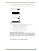
standard load. FIG. 38 shows a sample dimming curve.
Sometimes a fixture or lamp has a problem dimming down to a low range. When this happens, the lights
can flicker and cause unwanted dimming performance. To correct for anomalies in the dimming
performance of various devices, the AMX Lighting controller has provisions to set an individual low-end
trim for each of the six dimming channels. The AMX Lighting dimming system employs a low-end cut-
off that allows the dimmer to turn on to a specified level or to dim down to a specific level. The level at
which the dimmer turns on is called the Low End Setting. Low End commands prevent the dimmer from
going below a set threshold. They also force the dimmers on to the preset threshold, which is useful for
some transformer loads and track lights.
FIG. 38 Sample dimming curve