Operation/Reference Guide UPC20+ Universal Power Controller C o n t r o l S y s t e m A cc e s s o r i e s L a s t Re v is e d: 09 /1 2 /20 0 7
AMX Limited Warranty and Disclaimer AMX Corporation warrants its products to be free of defects in material and workmanship under normal use for three (3) years from the date of purchase from AMX Corporation, with the following exceptions: • Electroluminescent and LCD Control Panels are warranted for three (3) years, except for the display and touch overlay components that are warranted for a period of one (1) year.
UPC20+ Wiring Requirements ! In the United States, the UPC20+ must be wired by an authorized electrician in accordance with the National Electrical Code, ANSI/NFPA 70-1987, as well as all local codes. ! In the European community, the UPC20+ unit must be wired by an authorized electrician in accordance with all applicable European codes. A readily accessible disconnect device shall be incorporated into the fixed wiring.
Table of Contents Table of Contents UPC20+ Wiring Requirements ............................................................................3 Product Information ...........................................................................................1 Specifications .......................................................................................................... 3 Control Options Modes ............................................................................................
Table of Contents ii UPC20+ Universal Power Controller
Product Information Product Information The UPC20+ Universal Power Control is a dual 20 Amp AC power and motor controller designed for conduit installation. The UPC20+ is housed in a compact metal wall-mount enclosure and is configurable for a wide variety of power and motor control modes. Low voltage contact-closures, open collector inputs or serial data from an AMX IR receiver enable control by simple wall panels, remote systems, or hand-held transmitters.
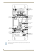
Product Information High voltage terminal and wiring arrangement label CAUTION RISK OF ELECTRIC SHOCK - MORE THAN ONE DISCONNECT SWITCH MAY BE REQUIRED TO DE-ENERGIZE THE EQUIPMENT BEFORE SERVICING GND IMPORTANT 5 6 SWITCH MUST MATCH INPUT VOLTAGE PRIOR TO APPLYING POWER TO UNIT 4 3 2 K2 1 P1 K1 B L K 12 A W G TO CIRCUIT BD ELECTRONICS USE COPPER ONLY 75°C INSULATION B L K 1 2 AWG High voltage wiring (120/240, 277 VAC) Power switch (115/230 VAC) Spade terminal block P1 Power and Motor con
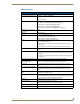
Product Information Specifications UPC20+ Specifications Power Self-powered when used with 110/220 VAC Power input (for control board) 120/240V ~, 50-60 Hz, 0.05/0.025A -or12 VDC, 0.2A max Power output per relay • 20A @ 120/240V ~, 50-60 Hz (RESISTIVE LOAD) • 6A @ 277V ~, 50-60 Hz (FLUORESCENT BALLAST) • 1 HP @ 120V ~, 50-60 Hz (INDUCTIVE LOAD) • 2 HP @ 240V ~, 50-60 Hz (INDUCTIVE LOAD) Total Current through both relays CAN NOT exceed 20 amp.
Product Information Control Options Modes ATTENTION INSTALLER FACTORY SET TO INOPERATIVE MODE (UNIT WILL NOT WORK UNTIL DIP SWITCHES ARE SET) SEE CHART ON LID TO SET DIP SWITCHES FOR ACTIVE MODE FIG. 2 UPC20+ inoperative mode warning label If UPC20+ is powered up when changes are made to Dip Switch settings, then power must be cycled before changes can take effect. Motor Control mode The table list options and connections for motor control.
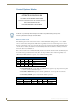
Product Information Power Control mode The tables below specify the DIP switch settings for momentary, latching, 2-button On/Off, and (momentary or latching) operation of K1 and K2.
Product Information The following table lists the DIP switch settings for Remote Sensor Mode. DIP Switch Settings for Remote Sensor Mode Sw. 1 Sw. 2 Sw. 3 Sw.
Installation Installation P1 Terminal Connections Low voltage power (see the table below) for internal circuitry is provided from an on-board transformer, powered by an external 120 or 240 VAC source. An onboard switch is used to select input voltage. When using the UPC20+ for 277 VAC control, the on-board internal circuitry is powered by a separate 120/240 VAC line, or from an optional 12 VDC power supply.
Installation UPC20+ Control Mode Functions for Inputs 1 and 2 Control Mode S2 Switch Setting R8 Motor Time Delay Pot Motor, Single Button On, On, Off, On Minimum Input 1 (P2, pin 5-to GND) Input 2 (P2, pin-6 to GND) Push 1 = load 1 "on" Not used Release 1 = load 1 "off" Push 1 again = load 2 "off" Minimum Push 1 = load 1 "on" Not used Release 1 = load 1 "off after delay time out" Push 1 again = load 2 "on" Release 1 again = load 2 "off after time out" Note: pushing again restarts cycle.
Installation UPC20+ Control Mode Functions for Inputs 1 and 2 (Cont.) Control Mode S2 Switch Setting R8 Motor Time Delay Pot Power, 2 Button On, Off, Off, On Minimum Maximum Input 1 (P2, pin 5-to GND) Input 2 (P2, pin-6 to GND) Push 1 = load 1 "on" Push 2 = load 2 "on" Release 1 = load 1 "still on" Release 2 = load 2 "still on" Push 1 = load 1 "on" Push 2 = load 2 "on" Release 1 = load 1 "still on" Release 2 = load 2 "still on" Note: Both loads can be On at the same time.
Installation UPC20+ Control Mode Functions for Inputs 3 and 4 (Cont.
Installation Dual circuit 277 VAC Dual circuit connections provide power from 277 VAC for fluorescent ballasts (FIG. 6). Circuit board power is provided by a separate 120/240 VAC high voltage circuit, or 12 VDC connected to terminals 1 and 6 on the low voltage terminal block. For dual circuit 120/240 VAC operation, remove the short 12 AWG wire jumper.
Installation Installing the UPC20+ To install the UPC20+ unit: 1. Mount the UPC20+ on a wall or solid surface in the location where it will be used; it can be mounted either horizontally or vertically. 2. Remove the cover. 3. Prepare terminal block P1. a. Set power switch S1. b. Configure jumpers according to high voltage wiring requirements. 4. Install conduit. Provide conduit for high voltage, low voltage and control wiring requirements using the 0.5 inch or 0.75 inch conduit connector knockouts. 5.
Installation UPC20+ Universal Power Controller 13
ARGENTINA • AUSTRALIA • BELGIUM • BRAZIL • CANADA • CHINA • ENGLAND • FRANCE • GERMANY • GREECE • HONG KONG • INDIA • INDONESIA • ITALY • JAPAN LEBANON • MALAYSIA • MEXICO • NETHERLANDS • NEW ZEALAND • PHILIPPINES • PORTUGAL • RUSSIA • SINGAPORE • SPAIN • SWITZERLAND • THAILAND • TURKEY • USA ATLANTA • BOSTON • CHICAGO • CLEVELAND • DALLAS • DENVER • INDIANAPOLIS • LOS ANGELES • MINNEAPOLIS • PHILADELPHIA • PHOENIX • PORTLAND • SPOKANE • TAMPA 3000 RESEARCH DRIVE, RICHARDSON, TX 75082 USA • 800.222.