
Corporation VSS2 Video Sync Sensor Instruction Manual


Installing The VSS2
6
VSS2 Video Sync Sensor
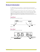
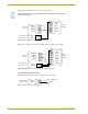
FIG. 6 shows a typical connection of a television manager.
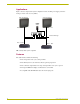
FIG. 7 shows a typical connection of a AMX control system and power supply.
12 VDC power supply connector
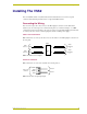
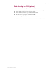
FIG. 8 shows how to connect the 12 VDC power to the rear panel.
I/O pin assignments are program dependent. Verify the wiring against the AXCESS
program documentation.
FIG. 6 Television manager and power supply wiring diagram
FIG. 7 AMX AXCENT Control System and power supply wiring diagram
FIG. 8 12 VDC power supply wiring diagram
Television
manager
Sense out
connecto
r
12 VDC powe
r
supply connector
GND2
SENSE2
GND1
SENSE1
PWR (+)
GND (-)
I/O 2
I/O 3
GND
I/O 1
I/O 4
PWR
GND2
Sense out
connecto
r
SENSE2
GND1
SENSE1
PWR (+)
GND (-)
12 VDC powe
r
supply connecto
r
I/O 2
I/O 3
GND
I/O 1
I/O 4
PWR
AMX
Control
System
I/O 5
I/O 6
A
B
12 VDC powe
r
supply connector
GND (-)
PWR (+)
12 VDC power
supply