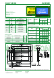
ANAG VISION AV241282 240 x 128 Graphic ° Built-in controller (T6963C or equivalent) ° +5V power supply ° NV built in ° 1/64 duty Pin Assignment No.
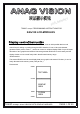
ANAG VISION RY A N IMI L PRE T6963C or equ. PROGRAMMING INSTRUCTIONS FOR 240x128 LCD-MODULES Displa y c ont rol inst ruc t ion The LCD Module has built in a T6963C LSI controller, It has an 8-bit parallel data bus and control lines for writing or reading through an MPU interface, it has a 128-word character generator ROM ( refer to Table 1. ), which can control an ex ternal display RAM of up to 8K bytes.
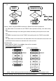
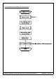
• Flowchart of communications with MPU (1) Status Read A status check must be performed before data is read or written. Status check The Status of T6963C can be read from the data lines.
(a) (b) (Note 4) When using the MSB=0 command, a Status Read must be performed. If a status check is not carried out, the T6963C cannot operate normally, even after a delay time. The hardware interrupt occurs during the address calculation period (at the end of each line). If a MSB=0 command is sent to the T6963C during this period, the T6963C enters Wait status.
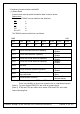
.COMMAND DEFINITIONS COMMAND CODE REGISTERS SETTING SET CONTROL WORD MODE SET DISPLAY MODE CURSOR PATTERN SELECT DATA AUTO READ/WRITE DATA READ/WRITE SCREEN PEEK 00100001 00100010 00100100 01000000 01000001 01000010 01000011 1000×000 1000×001 1000×011 1000×100 10000××× 10001××× 10010000 1001××10 1001××11 100101×× 100110×× 100111×× 10100000 10100001 10100010 10100011 10100100 10100101 10100110 10100111 10110000 10110001 10110010 11000000 11000001 11000010 11000011 11000100 11000101 11100000 D1 D2
.Setting registers CODE HEX. FUNCTION D1 D2 Y ADRS 00100001 21H SET CURSOR POINTER X ADRS 00100010 23H SET OFFSET REGISTER DATA 00100100 24H SET ADDRESS POINTER LOW ADRS 00H HIGH ADRS (1) Set Cursor Pointer The position of the cursor is specified by X ADRS and Y ADRS. The cursor position can only be moved by this command. Data read/write fr om the MPU never changes the cursor pointer. X ADRS and Y ADRS are specified as follows.
00010 11100 11101 11110 11111 (Example 1) Offset register Character code Character generator RAM start address 1000 to 17FFH E000 to E7FFH E800 to EFFFH F000 to F7FFH F800 to FFFFH 02H 80H 0001 0100 1 4 0000 0 0000 0 H (Example 2) The relationship between display RAM data and display characters γ and ζare displayed by character generator RAM. (3) Set Address Pointer The Set Address Pointer command is used to indicate the start address for writing to (or reading from) external RAM. T6963C or equ.
The Flowchart for Set Address Pointer command (upper 8 bits) T6963C or equ.
.Set Control Word CODE HEX. FUNCTION D1 01000000 40H Set Text Home Address 01000001 41H Set Text Area 01000010 42H Set Graphic Home Address 01000011 43H Set Graphic Area D2 Low address High address Columns 00H Low address Columns High address 00H The home address and column size are defined by this command. (1) Set Text Home Address The starting address in the external display RAM for text display is defined by this command.
(2) Set Graphic Home Address The starting address of the external display RAM used for graphic display is defined by this command. The graphic home address indicates the leftmost and uppermost position.
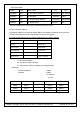
01E0H 01E1H - 01FEH 01FFH (3) Set Text Area The display columns are defined by the hardware Setting. This command can be used to adjust the columns of the display. (Example) LCD size 20 columns, 4lines Text home address 0000H Text area 0014H Set 32 columns, 4 Lines 0000 0001 ……… 0013 0014 ……… 001F 0014 0015 ……… 0027 0028 ……… 0033 0028 0029 ……… 003B 003C ……… 0047 003C 003D ……… 004F 0050 ……… 005B LCD (4) Set Graphic Area The display columns are defined by the hardware setting.
LCD If the graphic area setting is set to match the desired number of columns on the LCD, the addressing scheme will be automatically modified so that the start address of each line equals the end address of the previous line +1.
The attribute data for each character in the text area is written to the same address in the graphic area. The Attribute function is defined as follows.
• Cursor pattern select CODE FUNCTION OPERAND 10100000 1-line cursor - 10100001 2-line cursor - 10100010 3-line cursor - 10100011 4-line cursor - 10100100 5-line cursor - 10100101 6-line cursor - 10100110 7-line cursor - 10100111 8-line cursor - When cursor display is ON, this command selects the cursor pattern in the range 1 line to 8 lines. The cursor address is defined by the Cursor Pointer Set command. • Data Auto Read/Write CODE HEX.
a)Auto Read mode T6963C or equ.
T6963C or equ.
• Date Read/Write CODE H EX . FUNCT I ON OPERA ND 11000000 C0H Data Write and Increment ADP Data 11000001 C1H Data Read and Increment ADP 11000010 C2H Data Write and Decrement ADP 11000011 C3H Data Read and Decrement ADP - 11000100 C4H Data Write and Nonvariable ADP 11000101 C5H Data Read and Nonvariable ADP - - Data Data This command is used for writing data from the MP U to external display RAM, and reading data from external display RAM to the MPU.
• Screen Peek CODE 11100000 H EX . E0H FUNCT I ON Screen Peek OPERA ND -e This command is used to transfer 1 byte of displayeddata to the data stack; this byte can then be read from the MPU by data access. The logical combination of text and graphic display data on the LCD screen can be read by this command. The status (STA6) should be checked just after theScreen Peek command.
• Screen Copy CODE H EX . 11101000 E8H FUNCT I ON Screen Copy OPERA ND - This command copies a single raster line of data to the graphic area. The start point must be set usi ng the Set Address Pointer command. (Note 1) If the attribute function is being used, this command is not available. (With Attribute data is graphic area data.) Refer to the following flowchart. T6963C or equ.
• Bit Set/Reset CODE FUNCTION OPERAND 11110xxx Bit Reset - 11111xxx Bit Set - 1111x000 Bit 0 (LSB) - 1111x001 Bit 1 - 1111x010 Bit 2 - 1111x011 Bit 3 - 1111x100 Bit 4 - 1111x101 Bit 5 - 1111x110 Bit 6 - 1111x111 Bit 7 (MSB) - X: invalid This command use to set or reset a bit of the byte specified by the address pointer. Only one bit can be set/reset at a time. Refer to the following flowchart. T6963C or equ.
The intension of this document is to provide help if needed. It has been created with care, still the right for errors is reserved. With respect to any information carried out in this document, we take no warrenties, expressed or implied, including any warrenties of merchantability, the fitness for any particular purpose, infringement of any legal liability, responsibilty for the accuracy, the completeness and usefullness of any of these informations.