
Datasheet


PAGE: 5 OF 20
Y ADRS 00H to 0FH
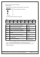
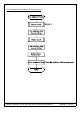
.Setting registers
CODE HEX. FUNCTION D1 D2
00100001 21H SET CURSOR POINTER X ADRS Y ADRS
00100010 23H SET OFFSET REGISTER DATA 00H
00100100 24H SET ADDRESS POINTER LOW ADRS HIGH ADRS
(1) Set Cursor Pointer
The position of the cursor is specified by X ADRS and Y ADRS. The cursor position can only
be moved by this command. Data read/write from the MPU never changes the cursor pointer.
X ADRS and Y ADRS are specified as follows.
X ADRS 00H to 4FH (lower 7 bits are valid)
Y ADRS 00H to 1FH (lower 5 bits are valid)
Single-Scan
X ADRS 00H to 4FH
(2) Set Offset Register
The offset register is used to determine the external character generator RAM area.
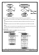
The T6963C has a 16-bit address bus as follows.
T6963C assign External character generator, when character code set 80H TO FFH in using
internal character generator. Character code 00H to 80H assign External character generator, when
External generator mode.
The senior five bits define the start address in external memory of the CG RAM area. The next
eight bits represent the character code of the character. In internal CG ROM, character codes 00H
to 7FH represent the predefined “internal” CG ROM characters, and codes 80H to FFH represent
the user’s own “external” characters. In extern al CG ROM mode, all 256 codes from 00H to FFH
can be used to represent the user’s own character s. The three least significant bits indicate one of
the eight rows of eight dots that define the character’s shape.
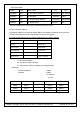
The relationship between display RAM address and offset register
Offset register data CG RAM hex. address (start to end)
00000 0000 to 07 FFH
00001 0800 to 0FFFH
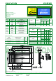
T6963C or equ.
driven 240X128 DOTS GRAPHIC MODULES