DPG10002-01, DPG10003-01, DPG10004-01 Microstep Driver Pack User’s Guide A N A H E I M A U T O M A T I O N 910 East Orangefair Lane, Anaheim, CA 92801 e-mail: info@anaheimautomation.com #L010167 (714) 992-6990 fax: (714) 992-0471 website: www.anaheimautomation.
DPG10002-01, DPG10003-01, DPG10004-01 Microstep Driver Pack Features • • • • • • • • • Integrated MBC10641, Power Supply, and Cooling Fan 90-265 VAC Input Output Current 10.0 Amps Peak 200 to 12,800 steps/rev (1,2,5,8,10,16,32 and 64 selectable step operations) Short Circuit Protection Motor Miss-Wire Detection No minimum Inductance Optical Isolation Motor ON/OFF Input Introduction The MBC10641 Microstep Driver has an output current capability of 1.5 Amps minimum to 10.0 Amps maximum (Peak Rating).
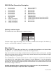
TB1: 8 Pin Terminal - All Connections INTERNALLY Wired to 25DB Port Pin # D escription 1 Step C lock Input Anode (+): A posi ti ve goi ng edge on thi s i solated i nput advances the motor one i ncrement. The si ze of the i ncrement i s dependent on the Mi crostep Select Inputs of Swi tch 1. 2 Step C lock Input C athode (-) 3 D irection Anode (+): Thi s i solated i nput i s used to change the di recti on of the motor. Physi cal di recti on also depends on the connecti on of the motor wi ndi ngs.
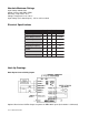
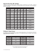
Absolute Maximum Ratings Input Voltage: 90-265 VAC Output Current: 10.0 AMPS PEAK Max Plate Temperature: 70° C Storage Temperature: 0° to +50° C Input Voltage (For isolated inputs): +5V to +24V at 2.5mA Electrical Specifications Item Min Input Voltage Typ Max Units 90 265 VAC Phase Output Current 1.0 7.1 A (RMS) Phase Output Current 1.5 10.0 A (PEAK) Clock Frequency 0 400 kHz Chopping Frequency 20 27 33 kHz +5VDC 4.8 5 5.
DB25 PIN Port Connection Description 1. 2. 3. 4. 5. 6. 7. 8 9. 10. 11. 12. 13. No Connection No Connection No Connection No Connection No Connection No Connection No Connection No Conneciton X Direction A Step ( Clock Input) Z Step ( Clock Input) Y Step ( Clock Input) X Step ( Clock Input) 14. 15. 16. 17. 18. 19. 20. 21. 22. 23. 24. 25.
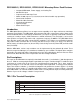
Microstep Selection (SW1 Settings) Switches 2, 3 and 4, of the DIP switch select the number of microsteps per step. Table 7 shows the standard resolution values along with the associated positions for the select switches. The standard waveforms are sinusoidal.
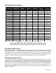
Step Motor Selection Guide Mo t o r Ex am p le Mo t o r Cu r r en t N u m b er C o d e U n i p o l ar R at i n g S er i es P eak R at i n g P ar al l el P eak R at i n g S er i es C u r r en t S et t i n g P ar al l el C u r r en t S et t i n g 23D 102S 02 1.0A 1.0A 2.0A ---- 5% 23L 303D-LW8 03 1.5A 1.5A 3.0A 0% 20% 34N104S-LW8 04 2.0A 2.0A 4.0A 5% 30% 23L 4005D-LW8 05 2.5A 2.5A 5.0A 10% 40% 34A 106B 06 3.0A 3.0A 6.0A 20% 50% 34N207S-LW8 07 3.5A 3.5A 7.
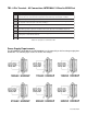
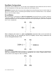
Step Motor Configurations Step motors can be configured as 4, 6, or 8 leads. Each configuration requires different currents. Refer to the lead configurations and the procedures to determine their output current. WARNING! Step motors will run hot even when configured correctly. Damage may occur to the motor if a higher than specified current is used. Most specified motor currents are maximum values. Care should be taken to not exceed these ratings.
8 Lead Motors Series Connection: When configuring the motor windings in series, use the per Phase (or unipolar) current rating to determine the current setting potentiometer value. Parallel Connection: When configuring the motor windings in parallel, multiply the per Phase (or unipolar) current rating by 2.0 to determine the current setting potentiometer value.
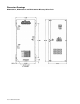
Dimension Drawings DPG10002-01, DPG10003-01 and DPG10004-01 Micostep Driver Pack User’s Guide # L010167
COPYRIGHT Copyright 2001 by Anaheim Automation. All rights reserved. No part of this publication may be reproduced, transmitted, transcribed, stored in a retrieval system, or translated into any language, in any form or by any means, electronic, mechanical, magnetic, optical, chemical, manual, or otherwise, without the prior written permission of Anaheim Automation, 910 E. Orangefair Lane, Anaheim, CA 92801.
Torque Speed Curves ANAHEIM AUTOMATION User’s Guide # L010167