
Datasheet


–8–
AD1854
REV. A
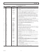
Burst Mode
To operate with SPI CCLK frequencies up to 12.288 MHz, the
SPI port can be operated in Burst Mode. This means that when
CLATCH is high, CCLK cannot be HI, as shown in Figure 7.
Mute
The AD1854 offers two methods of muting the analog output.
By asserting the MUTE (Pin 23) signal HI, both the left and
right channel are muted. As an alternative, the user can assert
the mute bit in the serial control register (Data 11) HI. The
AD1854 has been designed to minimize pops and clicks when
muting and unmuting the device.
Smooth Volume Control with Auto Ramp Up/Down
The AD1854 incorporates ADI’s 1024 step “Smooth Volume
Control” with auto ramp up/down. Once per L/RCLK cycle, the
AD1854 compares current volume level register to the volume
level request register Data 9:0. If different, volume is adjusted
one step/sample. Therefore, a change from max to min volume
takes 1024 samples or about 20 ms as shown in Figure 8.
20ms
TIME
–60
–60
0
0
LEVEL – dB
VOLUME REQUEST REGISTER
ACTUAL VOLUME REGISTER
Figure 8. Smooth Volume Control
Output Drive, Buffering and Loading
The AD1854 analog output stage is able to drive a 1 kΩ (in
series with 2 nF) load.
Power-Down Reset
The AD1854 offers two methods for power-down and reset.
When the PD/RST input (Pin 24) is asserted LO, the AD1854
is reset. As an alternative, the user can assert the soft power-
down bit (Data 13) HI. All the registers in the AD1854 digital
engine (serial data port, interpolation filter and modulator) are
zeroed. The two 8-bit registers in the serial control port are
initialized back to their default values. The user should wait
100 ms after bringing PD/RST HI before using the serial data
input port and the serial control input. The AD1854 is designed
to minimize pops and clicks when entering and exiting the power-
down state.
De-Emphasis
The AD1854 offers digital de-emphasis, supporting 50 µs/15 µs
digital de-emphasis intended for “Redbook” 44.1 kHz sample
frequency playback from Compact Discs. The AD1854 offers
control of de-emphasis by asserting the DEEMP input (Pin 9)
HI or by asserting the de-emphasis register bit (Data 12) HI.
The AD1854’s de-emphasis is optimized for 44.1 kHz but will
scale to the other sample frequencies.
Control Signals
The IDPM0, IDPM1, and DEEMP control inputs are normally
connected HI or LO to establish the operating state of the
AD1854. They can be changed dynamically (and asynchronously
to L/RCLK and the master clock) as long as they are stable
before the first serial data input bit (i.e., MSB) is presented to
the AD1854.
CLATCH
CCLK
20 40 60 80 100 120 140 160 180
CDATA
>130ns
TIME – ns
Figure 6. SPI Port Continuous CCLK Mode
CLATCH
CCLK
CDATA
TIME – ns
200 400 600 800 1000 1200 1400 1600 1800
Figure 7. SPI Port Burst Mode