
Datasheet


AD1939 Data Sheet
Rev. E | Page 4 of 32
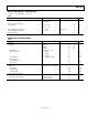
Parameter Conditions/Comments Min Typ Max Unit
Interchannel Phase Deviation 0 Degrees
Volume Control Step 0.375 dB
Volume Control Range 95 dB
De-emphasis Gain Error ±0.6 dB
Output Resistance at Each Pin
100
Ω
REFERENCE
Internal Reference Voltage FILTR pin 1.50 V
External Reference Voltage
FILTR pin
1.32
1.50
1.68
V
Common-Mode Reference Output CM pin 1.50 V
REGULATOR
Input Supply Voltage
VSUPPLY pin
4.5
5
5.5
V
Regulated Output Voltage VSENSE pin 3.19 3.37 3.55 V
Specifications measured at a case temperature of 125°C.
Table 2.
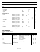
Parameter Conditions/Comments Min Typ Max Unit
ANALOG-TO-DIGITAL CONVERTERS
ADC Resolution All ADCs 24 Bits
Dynamic Range 20 Hz to 20 kHz, −60 dB input
No Filter (RMS)
93
102
dB
With A-Weighted Filter (RMS) 96 104 dB
Total Harmonic Distortion + Noise −1 dBFS −96 −87 dB
Full-Scale Input Voltage (Differential) 1.9 V rms
Gain Error −10 +10 %
Interchannel Gain Mismatch −0.25 +0.25 dB
Offset Error −10 0 +10 mV
DIGITAL-TO-ANALOG CONVERTERS
Dynamic Range 20 Hz to 20 kHz, −60 dB input
No Filter (RMS) 101 107 dB
With A-Weighted Filter (RMS) 104 110 dB
With A-Weighted Filter (Average) 112 dB
Total Harmonic Distortion + Noise 0 dBFS
Two channels running −94 dB
Eight channels running
−86
−70
dB
Full-Scale Output Voltage 1.76 (4.96) V rms (V p-p)
Gain Error −10 +10 %
Interchannel Gain Mismatch −0.2 +0.2 dB
Offset Error −25 −6 +25 mV
Gain Drift −30 +30 ppm/°C
REFERENCE
Internal Reference Voltage FILTR pin 1.50 V
External Reference Voltage FILTR pin 1.32 1.50 1.68 V
Common-Mode Reference Output CM pin 1.50 V
REGULATOR
Input Supply Voltage VSUPPLY pin 4.5 5 5.5 V
Regulated Output Voltage VSENSE pin 3.2 3.43 3.65 V
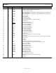
CRYSTAL OSCILLATOR SPECIFICATIONS
Table 3.
Parameter Min Typ Max Unit
Transconductance 3.5 mmhos