
Datasheet


AD2S80A
REV. B
–12–
180
–180
PHASE PLOT
f
BW
–90
–135
0.04f
BW
0.02f
BW
0
–45
45
90
135
0.4f
BW
0.2f
BW
0.1f
BW
FREQUENCY
2f
BW
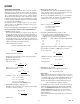
Figure 5. AD2S80A Phase Plot
OUTPUT
POSITION
TIME
t
2
t
1
Figure 6. AD2S80A Small Step Response
The small signal step response is shown in Figure 6. The time
from the step to the first peak is t
1
and the t
2
is the time from
the step until the converter is settled to 1 LSB. The times t
1
and
t
2
are given approximately by
t
1
=
1
f
BW
t
2
=
5
f
BW
×
R
12
where R = resolution, i.e., 10, 12, 14, or 16.
The large signal step response (for steps greater than 5 degrees)
applies when the error voltage exceeds the linear range of the
converter.
Typically the converter will take 3 times longer to reach the first
peak for a 179 degrees step.
In response to a velocity step, the velocity output will exhibit the
same time response characteristics as outlined above for the
position output.
ACCELERATION ERROR
A tracking converter employing a Type 2 servo loop does not
suffer any velocity lag, however, there is an additional error due
to acceleration. This additional error can be defined using the
acceleration constant K
A
of the converter.
K
A
=
Input Acceleration
Error in Output Angle
The numerator and denominator must have consistent angular
units. For example if K
A
is in sec
–2
, then the input acceleration
may be specified in degrees/sec
2
and the error output in degrees.
Angular measurement may also be specified using radians, min-
utes of arc, LSBs, etc.
K
A
does not define maximum input acceleration, only the error due
to it’s acceleration. The maximum acceleration allowable before
the converter loses track is dependent on the angular accuracy
requirements of the system.
Angular Accuracy × K
A
= Degrees/sec
2
K
A
can be used to predict the output position error for a
given input acceleration. For example for an acceleration of
100 revs/sec
2
, K
A
= 2.7 × 10
6
sec
–2
and 12-bit resolution.
Error in LSBs =
Input acceleration [LSB/sec
2
]
K
A
[sec
–2
]
=
100[rev/sec
2
] × 2
12
2.7 ×10
6
= 0.15 LSBs or 47.5 seconds of arc
To determine the value of K
A
based on the passive components
used to define the dynamics of the converter the following
should be used.
K
A
=
4.04 ×10
11
2
n
• R6• R4 •(C4 +C5)
Where n = resolution of the converter.
R4, R6 in ohms
C5, C4 in farads
12
–12
–6
–9
0.04f
BW
0.02f
BW
0
–3
3
6
9
0.4f
BW
0.2f
BW
0.1f
BW
FREQUENCY
GAIN PLOT
2f
BW
f
BW
Figure 4. AD2S80A Gain Plot