
Datasheet


AD5100
Rev. A | Page 18 of 36
Floating WDI Input
If the WDI pin is floating, the watchdog function is disabled by
default. However, floating watchdog can be enabled in the
RESET
configuration register such that a broken WDI connection or
any unusual condition that makes WDI float triggers the reset.
• Register 0x0D[3] = 0: floating WDI input does not activate
RESET
(Default)
• Register 0x0D[3] = 1: floating WDI input activates
RESET
This feature is fixed in OTP memory. Enabling or disabling the
floating WDI feature can be changed dynamically, using the
OTP overridden function is selected.
MANUAL RESET INPUT
Manual reset (
MR
) is an active low input to the AD5100 and
has an internal pull-up resistor to V
3MON
. If the input signal on
the
MR
pin goes low,
RESET
is activated.
MR
can be driven
from a CMOS logic signal.
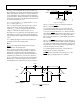
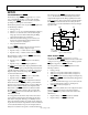
The
MR
and
RESET
timing diagrams are shown in .
Note that
Figure 15
RESET
is activated after t
MR_DELAY
and is held
for
t
RS_HOLD
after the
MR
signal has gone high again.
MR
has the highest priority in triggering the
RESET
over any
other monitoring inputs.
05692-015
t
MR
t
MR_DELAY
<
t
MR_GLITCH
t
RS_HOLD*
MR
* = PROGRAMMABLE
RESET
Figure 15. Manual Reset (
MR
) Timing Diagram