
Datasheet


AD536A Data Sheet
Rev. E | Page 6 of 16
PIN CONFIGURATIONS AND FUNCTION DESCRIPTIONS
V
IN
1
NC
2
–V
S
3
C
AV
4
+V
S
14
NC
13
NC
12
NC
11
dB
5
COM
10
BUF OUT
6
R
L
9
BUF IN
7
I
OUT
8
NC = NO CONNECT
AD536A
TOP VIEW
(Not to Scale)
00504-003
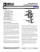
Figure 3. D-14 and Q-14 Packages Pin Configuration
Table 3. D-14 and Q-14 Packages Pin Function Descriptions
Pin No.
Mnemonic
Description
1 V
IN
Input Voltage
2 NC No Connection
3 −V
S
Negative Supply Voltage
4 C
AV
Averaging Capacitor
5 dB Log (dB) Value of the RMS Output Voltage
6 BUF OUT Buffer Output
7 BUF IN Buffer Input
8 I
OUT
RMS Output Current
9 R
L
Load Resistor
10 COM Common
11 NC No Connection
12 NC No Connection
13 NC No Connection
14
+V
S
Positive Supply Voltage
10
5
91
82
64
73
I
OUT
–V
S
V
IN
C
AV
+V
S
dB
COM
BUF OUT
R
L
BUF IN
AD536A
TOP VIEW
(Not to Scale)
00504-004
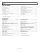
Figure 4. H-10 Package Pin Configuration
Table 4. H-10 Package Pin Function Descriptions
Pin No. Mnemonic Description
1
R
L
Load Resistor
2 COM Common
3 +V
S
Positive Supply Voltage
4 V
IN
Input Voltage
5 −V
S
Negative Supply Voltage
6 C
AV
Averaging Capacitor
7 dB Log (dB) Value of the RMS Output Voltage
8 BUF OUT Buffer Output
9 BUF IN Buffer Input
10 I
OUT
RMS Output Current