
Datasheet


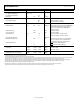


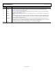


Table Of Contents

AD5700/AD5700-1 Data Sheet
Rev. F | Page 6 of 24
ABSOLUTE MAXIMUM RATINGS
T
A
= 25°C, unless otherwise noted.
Transient currents of up to 100 mA do not cause SCR latch-up.
Table 4.
Parameter Rating
V
CC
to GND −0.3 V to +7 V
IOV
CC
to GND −0.3 V to +7 V
Digital Inputs to DGND
−0.3 V to IOV
CC
+ 0.3 V or
+7 V (whichever is less)
Digital Output to DGND
−0.3 V to IOV
CC
+ 0.3 V or
+7 V (whichever is less)
HART_OUT to AGND −0.3 V to +2.5 V
HART_IN to AGND
−0.3 V to V
CC
+ 0.3 V or
+7 V (whichever is less)
ADC_IP
−0.3 V to V
CC
+ 0.3 V or
+7 V (whichever is less)
AGND to DGND −0.3 V to +0.3 V
Operating Temperature Range (T
A
)
Industrial −40°C to +125°C
Storage Temperature Range −65°C to +150°C
Junction Temperature (T
J
MAX
) 150°C
Power Dissipation (T
J
MAX
– T
A
)/θ
JA
Lead Temperature, JEDEC industry standard
Soldering J-STD-020
ESD
Human Body Model
(ANSI/ESDA/JEDEC JS-001-
2010)
8 kV
Field Induced Charge Model
(JEDEC JESD22_C101E)
1.5 kV
Machine Model
(ANSI/ESD S5.2-2009)
400 V
Stresses above those listed under Absolute Maximum Ratings
may cause permanent damage to the device. This is a stress
rating only; functional operation of the device at these or any
other conditions above those indicated in the operational
section of this specification is not implied. Exposure to absolute
maximum rating conditions for extended periods may affect
device reliability.
THERMAL RESISTANCE
θ
JA
is specified for the worst-case conditions, that is, a device
soldered in a circuit board for surface-mount packages.
Table 5. Thermal Resistance
Package Type θ
JA
1
θ
JC
Unit
24-Lead LFCSP 56 3 °C/W
1
Thermal impedance simulated values are based on JEDEC 2S2P thermal test
board with thermal vias. See JEDEC JESD51.
ESD CAUTION