AD592–SPECIFICATIONS (typical @ T = +258C, V = +5 V, unless otherwise noted) A Model Min ACCURACY Calibration Error @ +25°C1 TA = 0°C to +70°C Error over Temperature Nonlinearity2 TA = –25°C to +105°C Error over Temperature3 Nonlinearity2 OUTPUT CHARACTERISTICS Nominal Current Output @ +25°C (298.2K) Temperature Coefficient Repeatability4 Long Term Stability5 S AD592AN Typ Max Min AD592BN Typ Max 2.5 0.7 1.0 0.3 0.5 °C 1.8 0.15 3.0 0.35 0.8 0.1 1.5 0.25 0.4 0.05 0.8 0.15 °C °C 2.0 0.
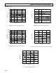
Typical Performance Curves–AD592 +2.0 +2.0 +1.5 +1.5 +1.0 +1.0 TOTAL ERROR – oC TOTAL ERROR – oC Typical @ VS = +5 V +0.5 0 –0.5 +0.5 0 –0.5 –1.0 –1.0 –1.5 –1.5 –2.0 –25 0 +25 +70 –2.0 +105 –25 0 +25 +70 +105 TEMPERATURE – oC TEMPERATURE – oC AD592CN Accuracy Over Temperature AD592BN Accuracy Over Temperature +2.0 0.75 +1.5 0.50 TOTAL ERROR – oC TOTAL ERROR – oC +1.0 +0.5 0 –0.5 0.25 0 –0.25 –1.0 –0.50 –1.5 –2.0 –25 0 +25 +70 –0.
AD592 resistor. Note that the maximum error at room temperature, over the commercial IC temperature range, or an extended range including the boiling point of water, can be directly read from the specifications table. All three error limits are a combination of initial error, scale factor variation and nonlinearity deviation from the ideal 1 µA/K output. Figure 2 graphically depicts the guaranteed limits of accuracy for an AD592CN.
AD592 +V SUPPLY VOLTAGE AND THERMAL ENVIRONMENT EFFECTS AD592 R 100Ω VOUT = 1mV/K 950Ω Figure 4. Basic Voltage Output (Single Temperature Trim) The power supply rejection characteristics of the AD592 minimizes errors due to voltage irregularity, ripple and noise. If a supply is used other than 5 V (used in factory trimming), the power supply error can be removed with a single temperature trim. The PTAT nature of the AD592 will remain unchanged.
AD592 Response of the AD592 output to abrupt changes in ambient temperature can be modeled by a single time constant τ exponential function. Figure 8 shows typical response time plots for several media of interest. +15V +5V AD592 AD592 AD592 100 A B 90 PERCENT OF FINAL TEMPERATURE C D AD592 333.3Ω (0.1%) 80 VTAVG (1mV/K) 10kΩ (0.
AD592 The circuit shown can be optimized for any ambient temperature range or thermocouple type by simply selecting the correct value for the scaling resistor – R. The AD592 output (1 µA/K) times R should approximate the line best fit to the thermocouple curve (slope in V/°C) over the most likely ambient temperature range. Additionally, the output sensitivity can be chosen by selecting the resistors RG1 and RG2 for the desired noninverting gain. The offset adjustment shown simply references the AD592 to °C.
To convert the AD592 output to °C or °F a single inexpensive reference and op amp can be used as shown in Figure 17. Although this circuit is similar to the two temperature trim circuit shown in Figure 6, two important differences exist. First, the gain resistor is fixed alleviating the need for an elevated temperature trim. Acceptable accuracy can be achieved by choosing an inexpensive resistor with the correct tolerance.