
Datasheet


Data Sheet AD633
Rev. J | Page 11 of 20
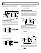
For example, if R = 8 kΩ and C = 0.002 µF, then Output A has a
pole at frequencies from 100 Hz to 10 kHz for E
C
ranging from
100 mV to 10 V. Output B has an additional 0 at 10 kHz (and
can be loaded because it is the low impedance output of the
multiplier). The circuit can be changed to a high-pass filter Z
interchanging the resistor and capacitor as shown in Figure 21.
AD633JN
X1
1
X2
2
Y1
3
Y2
4
+V
S
8
W
7
Z
6
–V
S
5
CONTROL
INPUT E
C
SIGNAL
INPUT E
S
0.1µF
0.1µF
+15V
–15V
00786-020
R
C
OUTPUT B
OUTPUT A
dB
f
1
f
2
f
+6dB/OCTAVE
OUTPUT A
OUTPUT B
0
Figure 21. Voltage-Controlled, High-Pass Filter
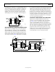
VOLTAGE-CONTROLLED QUADRATURE OSCILLATOR
Figure 22 shows two multipliers being used to form integrators
with controllable time constants in second-order differential
equation feedback loop. R2 and R5 provide controlled current
output operation. The currents are integrated in capacitors C1
and C2, and the resulting voltages at high impedance are applied
to the X inputs of the next AD633. The frequency control input,
E
C
, connected to the Y inputs, varies the integrator gains with a
calibration of 100 Hz/V. The accuracy is limited by the Y input
offsets. The practical tuning range of this circuit is 100:1. C2
(proportional to C1 and C3), R3, and R4 provide regenerative
feedback to start and maintain oscillation. The diode bridge, D1
through D4 (1N914s), and Zener diode D5 provide economical
temperature stabilization and amplitude stabilization at ±8.5 V
by degenerative damping. The output from the second integrator
(10 V sin ωt) has the lowest distortion.
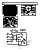
AUTOMATIC GAIN CONTROL (AGC) AMPLIFIERS
Figure 23 shows an AGC circuit that uses an rms-to-dc
converter to measure the amplitude of the output waveform.
The AD633 and A1, ½ of an AD712 dual op amp, form a
voltage-controlled amplifier. The rms-to-dc converter, an
AD736, measures the rms value of the output signal. Its output
drives A2, an integrator/comparator whose output controls the
gain of the voltage-controlled amplifier. The 1N4148 diode
prevents the output of A2 from going negative. R8, a 50 kΩ
variable resistor, sets the output level of the circuit. Feedback
around the loop forces the voltages at the inverting and
noninverting inputs of A2 to be equal, thus the AGC.
AD633JN
X1
1
X2
2
Y1
3
Y2
4
+V
S
8
W
7
Z
6
–V
S
5
0.1µF
0.1µF
C1
0.01µF
+15V
–15V
AD633JN
X1
1
X2
2
Y1
3
Y2
4
+V
S
8
W
7
Z
6
–V
S
5
0.1µF
+15V
–15V
R5
16kΩ
R3
330kΩ
R4
16kΩ
C3
0.01µF
C2
0.01µF
(10V) sin ωt
0.1µF
R2
16kΩ
R1
1kΩ
D5
1N5236
D1
1N914
D2
1N914
D3
1N914
D4
1N914
f =
E
C
10V
= kHz
(10V) cos ωt
E
C
00786-021
Figure 22. Voltage-Controlled Quadrature Oscillator