
Datasheet


Data Sheet AD633
Rev. J | Page 13 of 20
EVALUATION BOARD
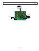
The evaluation board of the AD633 enables simple bench-top
experimenting to be performed with easy control of the
AD633. Built-in flexibility allows convenient configuration
to accommodate most operating configurations. Figure 24 is
a photograph of the AD633 evaluation board.
00786-024
Figure 24. AD633 Evaluation Board
Any dual-polarity power supply capable of providing 10 mA
or greater is all that is required, in addition to whatever test
equipment the user wishes to perform the intended tests.
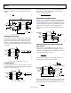
Referring to the schematic in Figure 31, inputs to the multiplier are
differential and dc-coupled. Three-position slide switches enhance
flexibility by enabling the multiplier inputs to be connected to
an active signal source, to ground, or to a test loop connected
directly to the device pin for direct measurements, such as bias
current. Inputs may be connected single ended or differentially,
but must have a dc path to ground for bias current. If an input
source’s impedance is non-zero, an equal value impedance must
be connected to the opposite polarity input to avoid introducing
additional offset voltage.
The AD633-EVALZ can be configured for multiplier or divider
operation by switch S1. Refer to Figure 16 for divider circuit
connections.
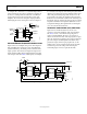
Figure 25 through Figure 28 are the signal, power, and ground-
plane artworks, and Figure 29 shows the component and circuit
side silkscreen. Figure 30 shows the assembly.
00786-026
Figure 25. Component Side Copper
00786-027
Figure 26. Circuit Side Copper
00786-028
Figure 27. Inner Layer Ground Plane