
Datasheet


A. Arrants 2
Software Needed (place attached files in directories listed below)
► VisualAnalog version 1.9.13.2 or higher
o AD6641_FFT_FIFO.vac canvas for VisualAnalog located at “C:\Program
Files\Analog Devices\VisualAnalog\Templates”
► SPIController version 1.0.57.3 or higher
o AD6641_12Bit_500MSspiR03.cfg and AD6641_12Bit_500MSspiR03.cal located
at “C:\ProgramData\Analog Devices\SPIController\Cfgs” for Vista or
“C:\Documents and Settings\All Users\Application Data\Analog
Devices\SPIController\Cfgs” for Windows XP.
► ad6641_fifo.bin FPGA configuration file located at “C:\Program Files\Analog
Devices\VisualAnalog\Hardware\HSC_ADC_EVALC”.
All documents and software are available at http://www.analog.com/fifo
.
For any questions please send an email to highspeed.converters@analog.com.
Testing
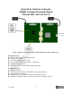
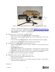
1. Connect the AD6641 evaluation board to the HSC-ADC-EVALCZ boards together as shown
in Figure 1.
2. Connect one 6V, 2A switching power supply (such as the CUI EPS060250UH-PHP-SZ
supplied) to the AD6641 board.
3. Connect one 5V, 3A (6V, 2A can optionally be used) switching power supply (such as the
CUI KSAFD0500300W1US supplied) to the HSC-ADC-EVALCZ board.
4. Connect the HSC-ADC-EVALCZ board to the PC with a USB cable. (Connect to J6.)
5. On the ADC evaluation board, make sure that jumpers are on headers J300 – J303 to connect
the power supplies. Connect pins 1 to 2 of P200 and pins 2 to 3 of P400 to connect the SPI
bus to the ADC.
6. On the ADC evaluation board, provide a clean, low jitter clock source to connector J200 at
the desired ADC conversion rate
7. On the ADC evaluation board, use a clean signal generator with low phase noise to provide
an input signal at connector J100. Use a 1 m, shielded, RG-58, 50 Ω coaxial cable to connect
the signal generator. For best results use a narrow-band, band-pass filter with 50 Ω
terminations and an appropriate center frequency. (ADI uses TTE, Allen Avionics, and K&L
band-pass filters.)
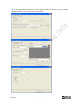
8. Open VisualAnalog on the PC. Under “New” tab, select AD6641 folder and the FFT template,
then click Open.
9. Expand the Canvas if necessary by clicking on the “Expand Canvas” button. Click the
“Settings” button of the “ADC Data Capture” block, click on the “Capture Board” tab. The
Program File should be ad6641_fifo.bin, use the browse button if not already displayed.
Click the “Program” Button. The ‘DONE’ LED should illuminate on the HSC-ADC-
EVALCZ board indicating that the FPGA has been correctly programmed. On the General