
Datasheet


AD7280A
Rev. 0 | Page 10 of 48
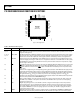
Pin No. Mnemonic Description
43 SDIhi
Serial Data Input in Daisy-Chain Mode. The data from each AD7280A in the daisy chain is passed through the
SDOlo output and the SDIhi input of each AD7280A in the chain and is supplied to the DSP/microprocessor
through the SDO output of the master AD7280A. This input should be connected to the SDOlo output of the
AD7280A immediately above it in potential in the daisy chain. The AD7280A at the highest potential in the
stack does not require a serial data input in daisy-chain mode; in this case, the pin should be connected to
V
DD
through a 1 kΩ resistor.
44
CNVSThi
Conversion Start Output in Daisy-Chain Mode. The convert start signal from the DSP/microprocessor supplied
to the CNVST
input of the master AD7280A is passed through each AD7280A by means of the CNVST input
and the CNVSThi
output. This output should be connected to the CNVST pin of the AD7280A immediately
above it in potential in the daisy chain. The AD7280A at the highest potential in the stack does not require
a daisy-chain conversion start output; in this case, the pin should be connected to V
DD
.
45 SDOhi
Serial Data Output in Daisy-Chain Mode. The serial data input from the DSP/microprocessor supplied to the
SDI input of the master AD7280A is passed through each AD7280A by means of the SDI input and the SDOhi
output. This output should be connected to the SDI input of the AD7280A immediately above it in potential
in the daisy chain. The AD7280A at the highest potential in the stack does not require a daisy-chain serial
data output; in this case, the pin should be connected to V
DD
.
46 SCLKhi
Serial Clock Output in Daisy-Chain Mode. The clock signal from the DSP/microprocessor supplied to the
SCLK input of the master AD7280A is passed through each AD7280A by means of the SCLK input and the
SCLKhi output. This output should be connected to the SCLK input of the AD7280A immediately above it in
potential in the daisy chain. The AD7280A at the highest potential in the stack does not require a daisy-chain
serial clock output; in this case, the pin should be connected to V
DD
.
47
CShi
Chip Select Output in Daisy-Chain Mode. The chip select signal from the DSP/microprocessor supplied to the
CS
input of the master AD7280A is passed through each AD7280A by means of the CS input and the CShi
output. This output should be connected to the CS
input of the AD7280A immediately above it in potential
in the daisy chain. The AD7280A at the highest potential in the stack does not require a daisy-chain chip
select output; in this case, the pin should be connected to V
DD
.
48
PDhi
Power-Down Output in Daisy-Chain Mode. The power-down signal from the DSP/microprocessor supplied
to the PD
input of the master AD7280A is passed through each AD7280A by means of the PD input and the
PDhi
output. This output should be connected to the PD input of the AD7280A immediately above it in
potential in the daisy chain. The AD7280A at the highest potential in the stack does not require a daisy-chain
power-down output; in this case, the pin should be connected to V
DD
.