
Datasheet


AD7280A
Rev. 0 | Page 4 of 48
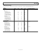
Parameter Min Typ Max Unit Test Conditions/Comments
REGULATOR OUTPUT (V
REG
)
Input Voltage Range 8 30 V
Output Voltage, V
REG
13
4.9 5.2 5.5 V 5 mA external load
Output Current
14
5 mA
Line Regulation 0.5 mV/V
Load Regulation 2.5 mV/mA
Internal Short Protection Limit 25 mA For a 10 Ω short
CELL BALANCING OUTPUTS
15
Output High Voltage, V
OH
V
REG
− 1 5 V
REG
+ 0.2 V I
SOURCE
= 415 nA
Output Low Voltage, V
OL
0 V
CB1 Output Ramp-Up Time
16
30 µs For an 80 pF load
CB1 Output Ramp-Down Time
17
30 µs For an 80 pF load
CB2 to CB6 Output Ramp-Up Time
16
380 µs For an 80 pF load
CB2 to CB6 Output Ramp-Down Time
17
30 µs For an 80 pF load
LOGIC INPUTS
Input High Voltage, V
INH
2.4 V
Input Low Voltage, V
INL
0.4 V
Input Current, I
IN
±10 µA
Input Capacitance, C
IN
5 pF
LOGIC OUTPUTS
Output High Voltage, V
OH
V
DRIVE
× 0.9 V I
SOURCE
= 200 µA
Output Low Voltage, V
OL
0.4 V I
SINK
= 200 µA
Floating State Leakage Current ±10 µA
Floating State Output Capacitance 5 pF
Output Coding Straight binary
1
For dc accuracy specifications, the LSB size for cell voltage measurements is (2 × V
REF
− 1 V)/4096. The LSB size for auxiliary ADC input voltage measurements is (2 × V
REF
)/4096.
2
ADC unadjusted error includes the INL of the ADC and the gain and offset errors of the VIN0 to VIN6 input channels.
3
The conversion accuracy during cell balancing is decreased due to the activation of the cell balance circuitry. The ADC unadjusted error increases by a factor of 4.
4
Total unadjusted error includes the INL of the ADC and the gain and offset errors of the VIN0 to VIN6 input channels, as well as the reference error, that is, the difference between
the ideal and actual reference voltage and the temperature coefficient of the 2.5 V reference.
5
The conversion accuracy during cell balancing is decreased due to the activation of the cell balance circuitry. The total unadjusted error increases by a factor of 4.
6
For the full analog input range, that is, 1 V to 2 × V
REF
, the total unadjusted error increases by 20%.
7
The total current measured on the input pins while converting is the sum of the static and dynamic leakage currents. See the Terminology section.
8
Bit D3 of the control register is set to 0 (thermistor termination resistor function is not in use).
9
ADC unadjusted error includes the INL of the ADC and the gain and offset errors of the AUXx input channels.
10
Total unadjusted error includes the INL of the ADC and the gain and offset errors of the AUXx input channels, as well as the reference error, that is, the difference between the
ideal and actual reference voltage and the temperature coefficient of the 2.5 V reference.
11
The turn-on settling time is the time from the rising edge of the
PD
signal until the conversion result settles to the specified accuracy. This includes the time required
to power up the regulator and the reference. Note that a rising edge on the
CNVST
input is also required to power up the reference. This rising edge should occur after
the rising edge on
PD
.
12
Sample tested during initial release to ensure compliance.
13
The regulator output voltage is specified with an external 5 mA load in addition to the current required to drive the AV
CC
, DV
CC
, and V
DRIVE
supplies of the AD7280A.
14
This specification refers to the maximum regulator output current that is available for external use.
15
The CBx outputs can be set to 0 V or V
REG
with respect to the negative terminal of the cell being balanced.
16
The CB1 to CB6 output ramp-up times are defined from the rising edge of the
CS
command until the CB output exceeds V
REG
− 1 V with respect to the negative
terminal of the cell being balanced.
17
The CB1 to CB6 output ramp-down times are defined from the rising edge of the
CS
command until the CB output falls below 50 mV with respect to the negative
terminal of the cell being balanced.