
Datasheet


AD7280A
Rev. 0 | Page 9 of 48
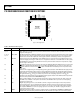
Pin No. Mnemonic Description
21
CS
Chip Select Input. The CS input is used to frame the input and output data on the SPI and daisy-chain
interfaces. On the master AD7280A device, the CS
input is supplied from the DSP/microprocessor. When
the AD7280A acts as a slave in a daisy chain, this input should be connected to the CShi
output of the
AD7280A immediately below it in potential in the daisy chain.
22 SCLK
Serial Clock Input. On the master AD7280A device, the SCLK input is supplied from the DSP/microprocessor.
When the AD7280A acts as a slave in a daisy chain, this input should be connected to the SCLKhi output of
the AD7280A immediately below it in potential in the daisy chain.
23 SDI
Serial Data Input. Data to be written to the on-chip registers is provided on this input and is clocked into the
AD7280A on the falling edge of the SCLK input. On the master AD7280A device, SDI is the data input of the
SPI interface. When the AD7280A acts as a slave in a daisy chain, this input accepts data from the SDOhi
output of the AD7280A immediately below it in potential in the daisy chain.
24
CNVST
Convert Start Input. The conversion is initiated on the falling edge of CNVST. On the master AD7280A, the
CNVST
pulse is supplied from the DSP/microprocessor; this input can also be tied to DV
CC
and the conversion
initiated through the serial interface. When the AD7280A acts as a slave in a daisy chain, this input should be
connected to the CNVSThi
output of the AD7280A immediately below it in potential in the daisy chain.
25 SDOlo
Serial Data Output in Daisy-Chain Mode. On the master AD7280A device, this output should be connected
to V
SS
either directly or through a pull-down, 1 kΩ resistor. When the AD7280A acts as a slave in a daisy chain,
this output should be connected to the SDIhi input of the AD7280A immediately below it in potential in the
daisy chain.
26 SDO
Serial Data Output. The conversion output data or the register output data is supplied to this pin as a serial
data stream. The bits are clocked out on the rising edge of the SCLK input; 32 SCLKs are required to access
the data. On the master AD7280A device, the SDO output should be connected to the DSP/microprocessor.
The SDO outputs of the remaining AD7280As in the daisy chain should be connected to V
SS
either directly or
through a pull-down, 1 kΩ resistor.
27 ALERT
Digital Output. This flag indicates cell or auxiliary ADC input overvoltage or undervoltage. The ALERT output of
the master AD7280A should be connected to the DSP/microprocessor. The ALERT outputs of the remaining
AD7280As in the daisy chain should be connected to V
SS
either directly or through a pull-down, 1 kΩ resistor.
28 ALERTlo
Alert Output in Daisy-Chain Mode. On the master AD7280A, this output should be connected to V
SS
either
directly or through a pull-down, 1 kΩ resistor. When the AD7280A acts as a slave in a daisy chain, this output
should be connected to the ALERThi input of the AD7280A immediately below it in potential in the daisy chain.
29 V
DRIVE
Logic Power Supply Input. The voltage supplied at this pin determines the voltage at which the SPI interface
operates. This pin should be decoupled to DGND. On the master AD7280A device, the voltage range on this
pin is 2.7 V to 5.5 V. The V
DRIVE
voltage can be different from the voltage at AV
CC
and DV
CC
, but it should never
exceed either by more than 0.3 V. The V
DRIVE
pin of the remaining AD7280As in the daisy chain should be
connected to V
REG
.
30 AV
CC
Analog Supply Voltage for the ADC Core, 4.9 V to 5.5 V. The AV
CC
and DV
CC
voltages should ideally be at the
same potential. For best performance, it is recommended that the AV
CC
and DV
CC
pins be shorted together to
ensure that the voltage difference between them never exceeds 0.3 V, even on a transient basis. This supply
should be decoupled to AGND. Place 100 nF decoupling capacitors on the AV
CC
pin. The AV
CC
supply pin
should be connected to the V
REG
output.
31 AGND
Analog Ground. This pin is the ground reference point for all analog circuitry on the AD7280A. This input should
be at the same potential as the base of the series-connected battery cells. The AGND and DGND voltages
should ideally be at the same potential and must not be more than 0.3 V apart, even on a transient basis.
32 AUX
TERM
Thermistor Termination Resistor Input. If this function is not required in the application, it is recommended
that this pin be connected to V
REG
through a 10 kΩ resistor.
33 to 38 AUX6 to AUX1
Auxiliary, Single-Ended 5 V ADC Inputs. If any of these inputs is not required in the application, it is
recommended that the pin be connected to V
REG
through a 10 kΩ resistor.
39 C
REF
Reference Capacitor. A 100 nF decoupling capacitor to REFGND should be placed on this pin.
40 V
REF
Reference Output, 2.5 V. The on-chip reference is available on this pin for use external to the AD7280A.
A 1 µF decoupling capacitor to REFGND is recommended on this pin.
41 REFGND
Reference Ground. This pin is the ground reference point for the internal band gap reference circuitry on
the AD7280A. The REFGND voltage should be at the same potential as the AGND voltage.
42 ALERThi
Alert Input in Daisy-Chain Mode. The alert signal from each AD7280A in the daisy chain is passed through
the ALERTlo output and the ALERThi input of each AD7280A in the chain and is supplied to the DSP/micro-
processor through the ALERT output of the master AD7280A. This input should be connected to the ALERTlo
output of the AD7280A immediately above it in potential in the daisy chain. The AD7280A at the highest
potential in the stack does not require an alert input; in this case, the pin should be connected to V
DD
through a 1 kΩ resistor.